Heat exchanger

a heat exchanger and platefin technology, applied in indirect heat exchangers, laminated elements, lighting and heating apparatus, etc., can solve the problems of increasing equipment costs and operating costs, increasing pump power, etc. reducing pressure loss, and reducing pressure loss

Inactive Publication Date: 2006-05-04
KATO YASUYOSHI
View PDF7 Cites 53 Cited by
  • Summary
  • Abstract
  • Description
  • Claims
  • Application Information

AI Technical Summary

Benefits of technology

[0020] As described above, in the heat exchanger according to the present invention, the heat exchanger fins are formed so as to have a cross-sectional shape formed by a curve such as an S-shaped curve, that is, a cross-sectional shape formed by a pseudo sine curve or the like and the area of the fluid channel, through which a fluid flows between the two adjacent heat exchanger fins, are made substantially uniform at any place in the flow direction of the fluid. As a result, a variation in the fluid channel area decreases, so that it is possible to reduce pressure loss resulting from the contracted and expanded ...

Problems solved by technology

Because of this, there has been a disadvantage in that increased pressure losses of the fluid c...

Method used


Image

  • Heat exchanger
  • Heat exchanger
  • Heat exchanger

Examples


Embodiment Construction

[0037] An embodiment of the invention will be explained below with reference to drawings.

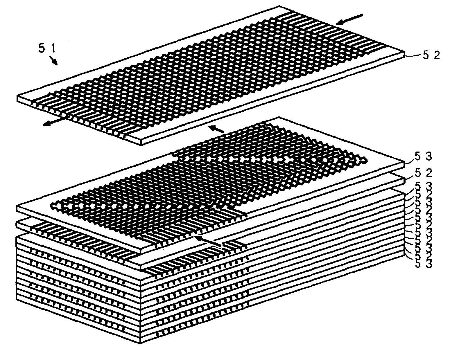
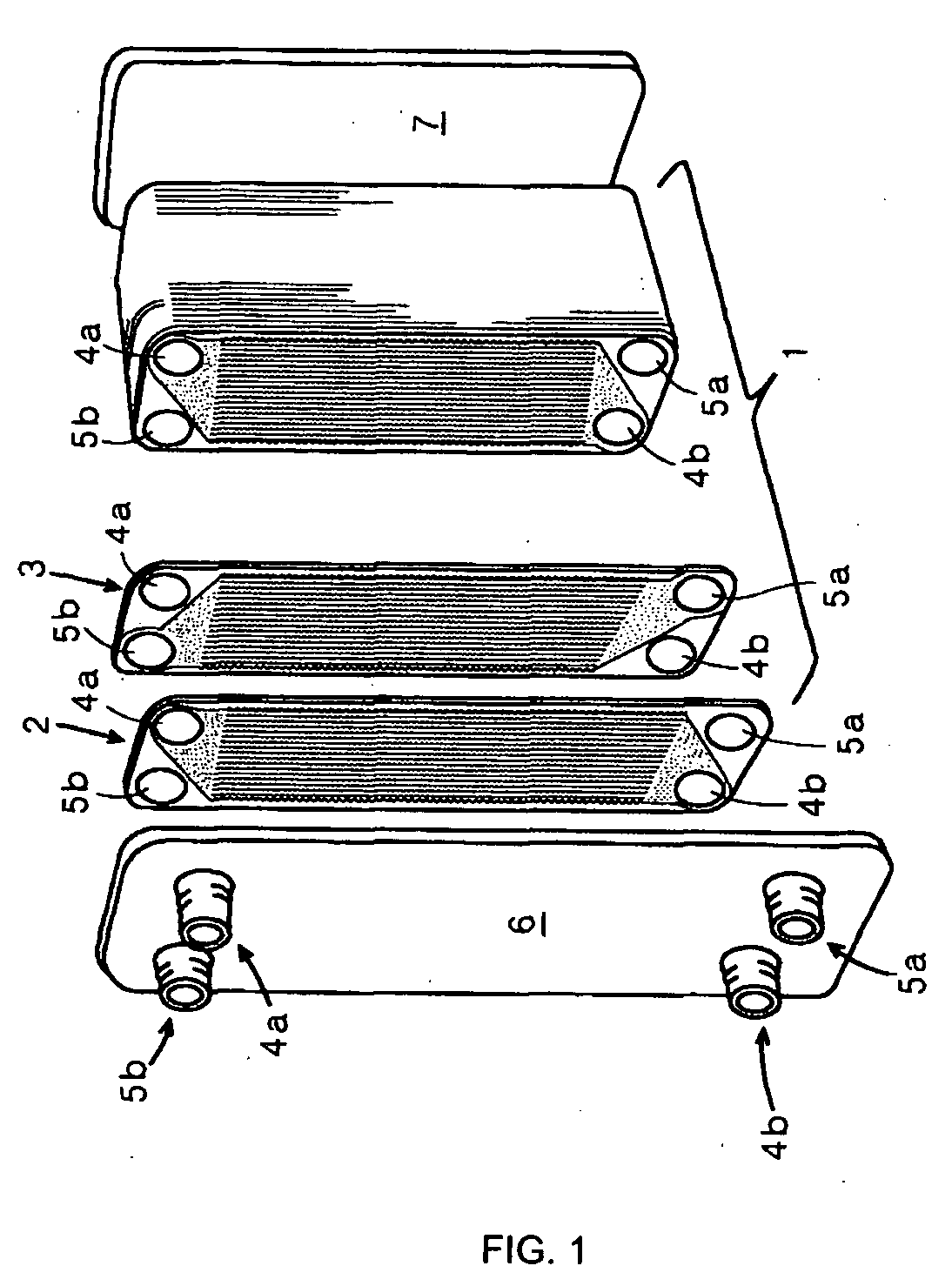
[0038]FIG. 1 is a schematic diagram of the appearance of a heat exchanger according to the invention. In FIG. 1, thin metal plates 2, through which a high-temperature (hot) side fluid flows, and thin metal plates 3, through which a low-temperature (cold) side fluid flows, are stacked. Plates 6 are attached to the uppermost surfaces of the metal plates 2 and 3 and bottom plates 7 are attached to the lowermost surfaces of the metal plates 2 and 3 to form a box-shaped heat exchanger body 1.

[0039] The thin metal plates 2 and 3, which constitute the heat exchanger body 1, are made of an about a several mm thick stainless steel plate, a copper plate, a titanium plate, or the like. In addition, the thin metal plates 2 and 3 are firmly joined together by using compression bonding at a temperature close to their melting points or any other method in such a way that metallic atoms, which constitute the ...


PUM


Abstract

To reduce pressure loss on a heat-exchanger fluid while downsizing a heat exchange and reducing the production cost of the heat exchanger without impairment of the heat transfer performance of the heat exchanger by forming a fluid channel in surfaces of thin metal plates such as stainless steel plates through the use of an etching technique or the like and by improving the shape of the fluid channel. In a heat exchanger in which a plurality of heat exchanger fins are provided in thin metal plates by using an etching technique or the like and a fluid channel for a heat-exchanger fluid is formed between the two opposed thin metal plates by alternately stacking the thin metal plates, the area of the fluid channel, through which the fluid flows between the heat exchanger fins, is made substantially uniform by forming the heat exchanger fins so as to have a curved cross-sectional shape from the front end thereof to the rear end.

Description

BACKGROUND OF THE INVENTION [0001] 1. Field of the Invention [0002] The present invention relates to a plate-fin type heat exchanger used for transferring heat between two fluids on high- and low-temperature sides different in temperatures. [0003] 2. Description of the Prior Art [0004] In general, heat exchangers are widely used for the utilization of heat energy, equipment requiring heat removal and so on. Among them, there is a plate-fin type heat exchanger as a typical high-performance heat exchanger. The plate-fin type heat exchanger has a structure in which thin metal plates formed by press working or the like are stacked, and then opposed, cross, or parallel fluid channels of two heat-exchanger fluids of high temperature (hot) side fluid and low temperature (cold) side fluid are formed between the thin metal plates. [0005] Moreover, to increase heat transfer efficiency between two heat-exchanger fluids different in temperature, heat exchangers have been produced so as to incre...

Claims


Application Information

Patent Timeline
IPC IPC(8): F28F3/00
CPCF28D9/005F28F3/048F28F13/06F28F2250/02
Inventor KATO, YASUYOSHIISHIZUKA, TAKAOTSUZUKI, NOBUYOSHI
Owner KATO YASUYOSHI
Why Eureka
Try Eureka