Positive air flow drive train unite for utility vehicle

a technology of drive train and positive air flow, which is applied in the direction of electric propulsion mounting, jet propulsion mounting, cycle, etc., can solve the problems of insufficient design, insufficient operation of the fins, and difficulty in achieving the effect of high air pressur

Inactive Publication Date: 2006-05-04
BUSH HOG L L C
View PDF18 Cites 27 Cited by
  • Summary
  • Abstract
  • Description
  • Claims
  • Application Information

AI Technical Summary

Benefits of technology

[0013] In accordance with the present invention, a positive air flow drive train unit for a utility vehicle not only cools CVT components but also provides an enclosure or housing having a positive air flow in order to thereby maintain clean conditions within the enclosure, even during the idle mode of the utility vehicle engine. A CVT primary clutch, CVT secondary clutch, and a CVT belt are disposed within the interior of the housing. Preferably, the CVT housing is defined by a cover weldment, a base plate weldment, and a peripheral wall. The peripheral wall includes an inlet port for receiving positive air flow into the housing and an outlet port for the exhaust of air from within the housing. An intake fan associated with the inlet port continuously impels filtered ambient air into the housing, which creates a region of relatively high air pressure therein. The outlet port allows for pressure equalization within the housing and also vents hot air from within the CVT housing. In a preferred embodiment, the inlet and outlet ports are spaced sufficiently far apart such that the air impelled into the housing must cross all of the CVT components disposed therein before exiting through the outlet port and provides positive air pressure throughout the CVT housing.

Problems solved by technology

Thus, operation of the fins is not independent of operation of the CVT.
Air flow is imparted only when the CVT is in operation, but that has been found to be insufficient because the CVT is subject to intrusion by dirt, rainwater, and the like even when the vehicle is in idle mode.
This proposed design is problematic.
Furthermore, adequate cooling of the drive components is not assured, and the pressure along the seams of the housing can be insufficient to reliably prevent the intrusion of moisture and outside particulates.

Method used


Image

  • Positive air flow drive train unite for utility vehicle
  • Positive air flow drive train unite for utility vehicle
  • Positive air flow drive train unite for utility vehicle

Examples


Embodiment Construction

[0023] As required, detailed embodiments of the present invention are disclosed herein; however, it is to be understood that the disclosed embodiments are merely exemplary of the invention, which may be embodied in various forms. Therefore, specific details disclosed herein are not to be interpreted as limiting, but merely as a basis for the claims and as a representative basis for teaching one skilled in the art to variously employ the present invention and virtually any appropriate manner.

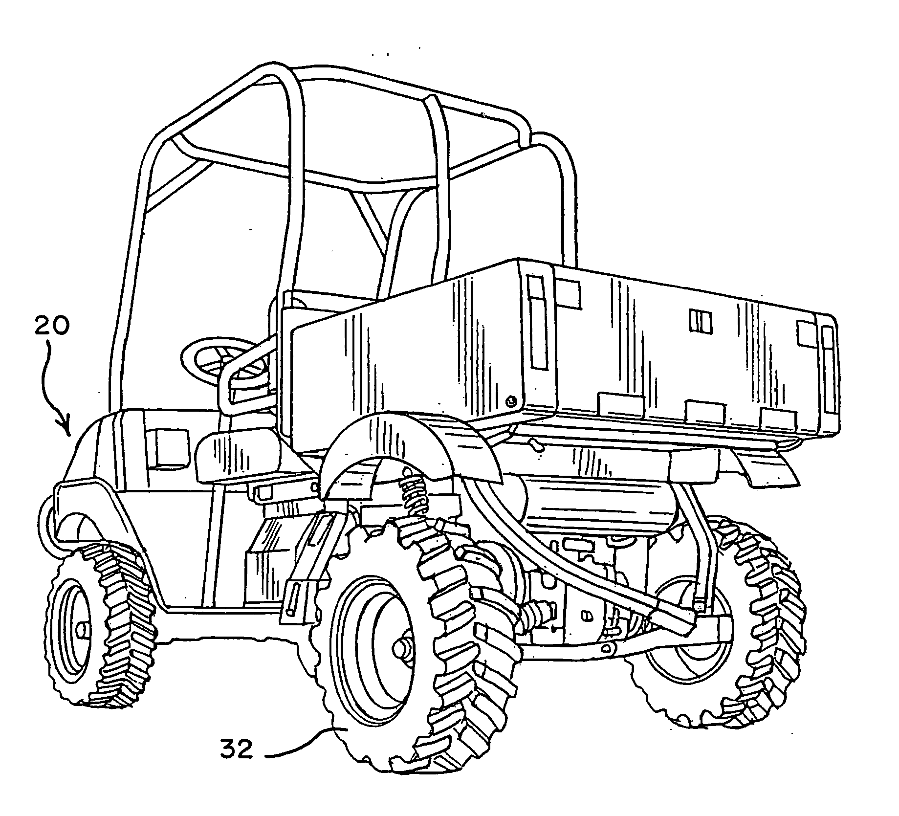
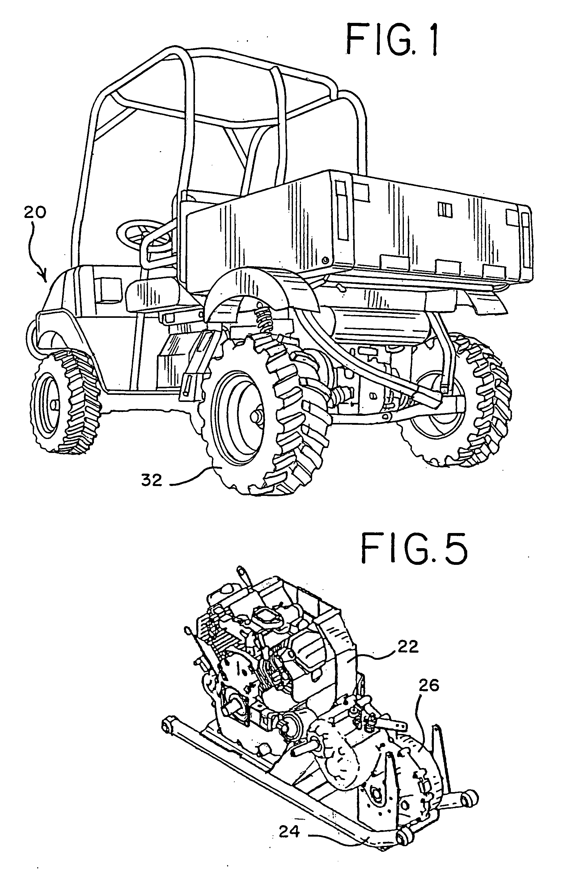
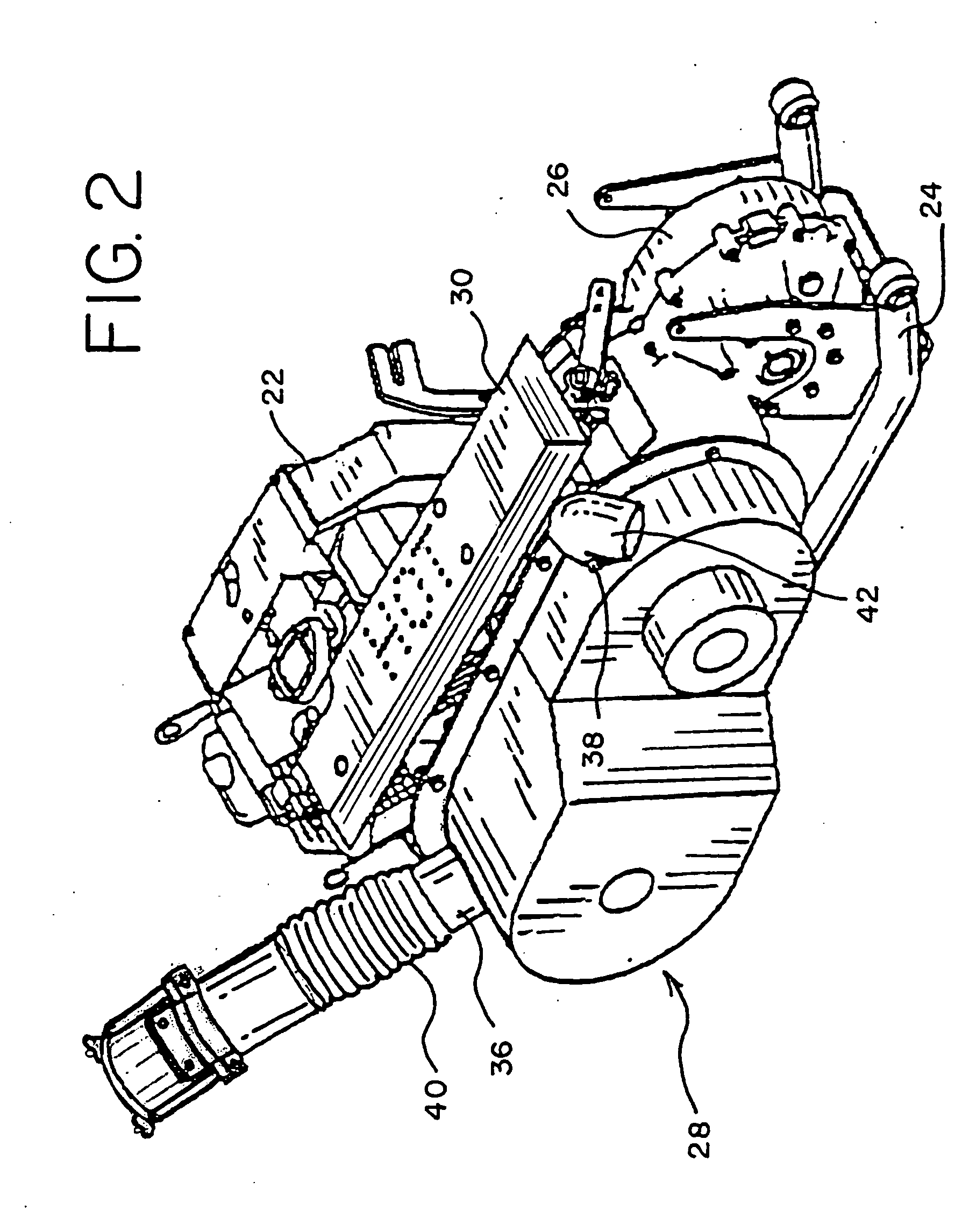
[0024]FIG. 1 shows a typical rear-engine utility vehicle 20 which is suitable for use with a CVT unit according to the present invention. The preferred embodiment that is illustrated in FIGS. 2 and 3 includes an engine 22 which is of a type and size suitable for use within a utility vehicle 20. The engine 22 is disposed on top of an engine mount sub-assembly 24, which also carries a two speed transaxle 26. Disposed adjacent to the engine 22 is the CVT housing, generally designated at 28, as well...


PUM


Abstract

A utility vehicle is provided which has a CVT drive unit. A housing for the drive unit provides an enclosure for the CVT drive components and defines an air flow path. An inlet port associated with the CVT housing includes a fan assembly which provides a source for filtered ambient air flow into the CVT housing. An outlet port associated with the CVT housing provides an exit for the air flow path and equalizes pressure within the enclosure. The interior of the housing is pressurized with ambient air in order to cool the CVT components therein. The pressurized air also creates an air curtain which prevents moisture and debris from intruding into the housing. Preferably the fan is powered separately from the engine of the utility vehicle to ensure positive air flow into the CVT housing even when the engine is in idle mode.

Description

CROSS REFERENCE TO RELATED APPLICATION [0001] Provisional Patent Application Ser. No. 60 / 543,161, filed Feb. 10, 2004.BACKGROUND OF THE INVENTION [0002] 1. Field of the Invention [0003] This invention generally relates to a drive train system for utility vehicles. A positive pressure approach is used in maintaining air flow through a drive train enclosure. Special application is found for this approach in continuously variable transmissions suitable for use on utility vehicles. The positive pressure achieved by this invention prevents dust and water from entering the transmission enclosure at virtually all times during operation of the vehicle. More particularly, the invention relates to a positive air flow system that operates independently of transmission rotation or operation. [0004] 2. Description of Related Art [0005] Utility vehicles of the type which are suitable for all-terrain usage and the like are provided. Utility vehicles are generally four-wheeled vehicles, which are o...

Claims


Application Information

Patent Timeline
Patent Type & Authority Applications(United States)
IPC IPC(8): B60K11/00B60K11/06B60K17/00F16H57/04
CPCF16H57/0415F16H57/0489Y10S180/908
Inventor HASTINGS, DAWSONW
Owner BUSH HOG L L C
Why Eureka
Try Eureka