
Hovering Wind Turbine

a wind turbine and rotor technology, applied in the direction of machines/engines, renewable energy generation, electric generator control, etc., can solve the problems of increasing the cost of kilowatt-hour, and affecting the operation of wind turbines in offshore sites. , to achieve the effect of reducing the cost per kilowatt-hour and reducing the siz

Inactive Publication Date: 2006-05-04
MACEDO ALEANDRO SOARES
View PDF10 Cites 11 Cited by
  • Summary
  • Abstract
  • Description
  • Claims
  • Application Information

AI Technical Summary

Benefits of technology

"The patent describes a type of wind turbine that moves in a closed cylindrical path and changes its pitch angle to capture wind energy. It can be attached to a lighter-than-air balloon to stay airborne in light winds. The turbine can reach higher altitudes where stronger wind power is available. The patent includes drawings of a four-bladed version of the turbine and a two-bladed version with a crank handle drum. The patent also describes an array of these turbines. The technical effect of the invention is a wind turbine that can efficiently capture wind energy in a compact design that can reach higher altitudes for better wind power production."

Problems solved by technology

The kitecraft solution would be impractical during periods of very light winds or would put the structure in danger during windstorms.
The device uses a winch at ground level for winding and unwinding the tether to be brought down during long periods of light wind; therefore it requires a landing field, which makes its operation, especially in offshore sites, more challenging.
Due to safety issues, a complex and very reliable control system is needed for its autonomous operation.

Method used


Image

  • Hovering Wind Turbine
  • Hovering Wind Turbine
  • Hovering Wind Turbine

Examples


Embodiment Construction

—PREFERRED EMBODIMENT

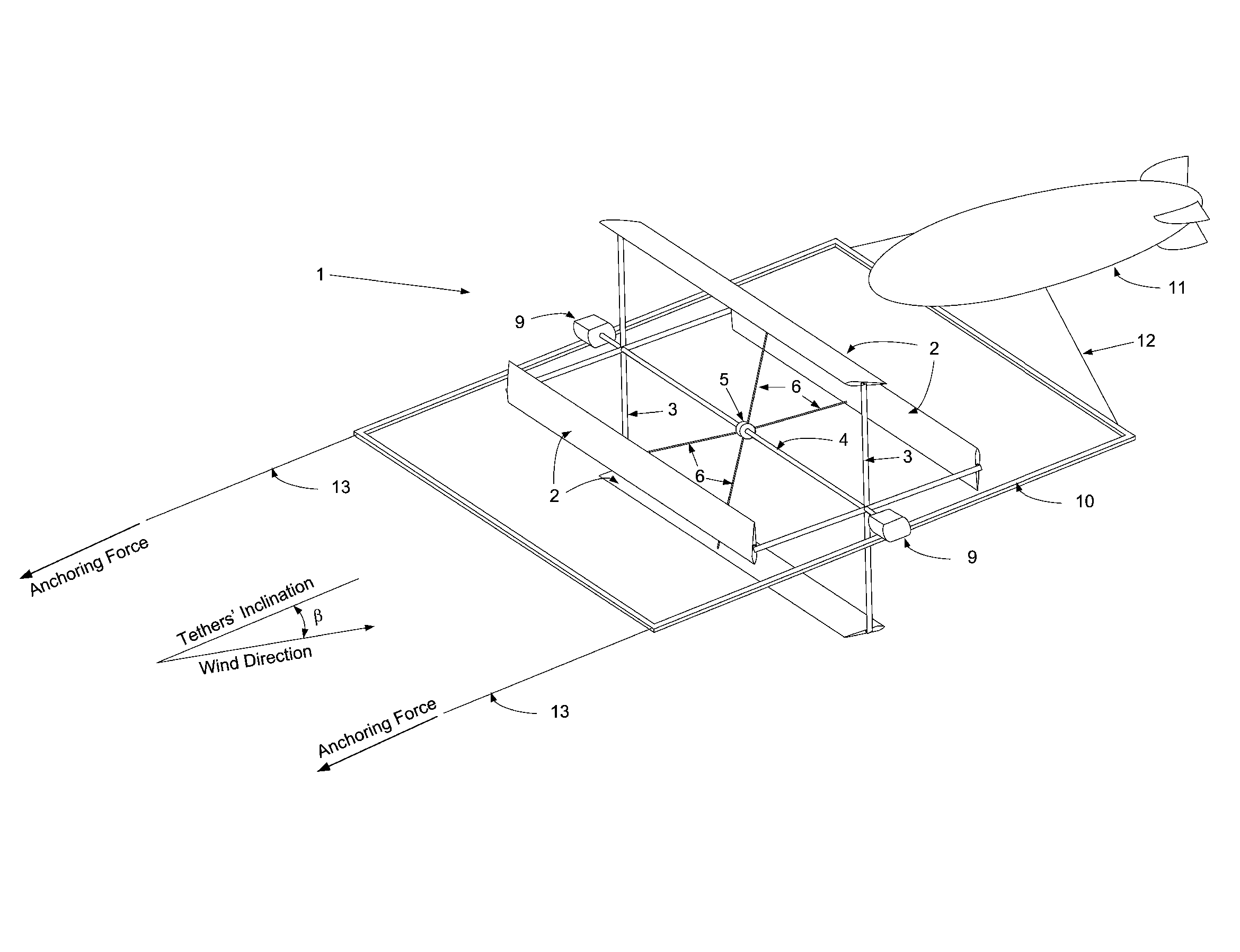
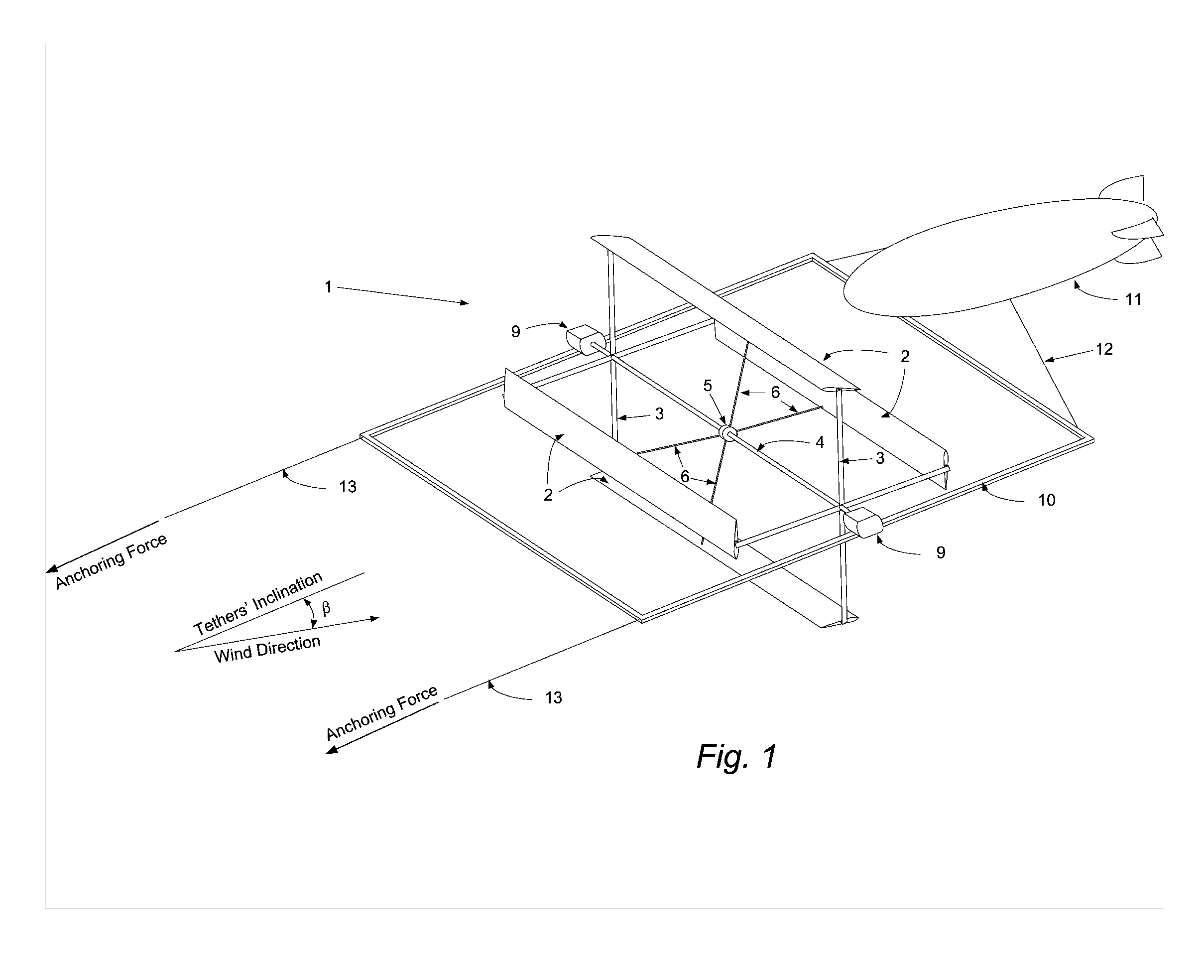
[0042] The preferred embodiment of the hovering wind turbine 1 of the present invention is illustrated in FIG. 1.

[0043] Articulated joints (not shown) connect the two ends of blade 2 to blade arms 3. The other ends of arms 3 are connected to turbine axle 4.

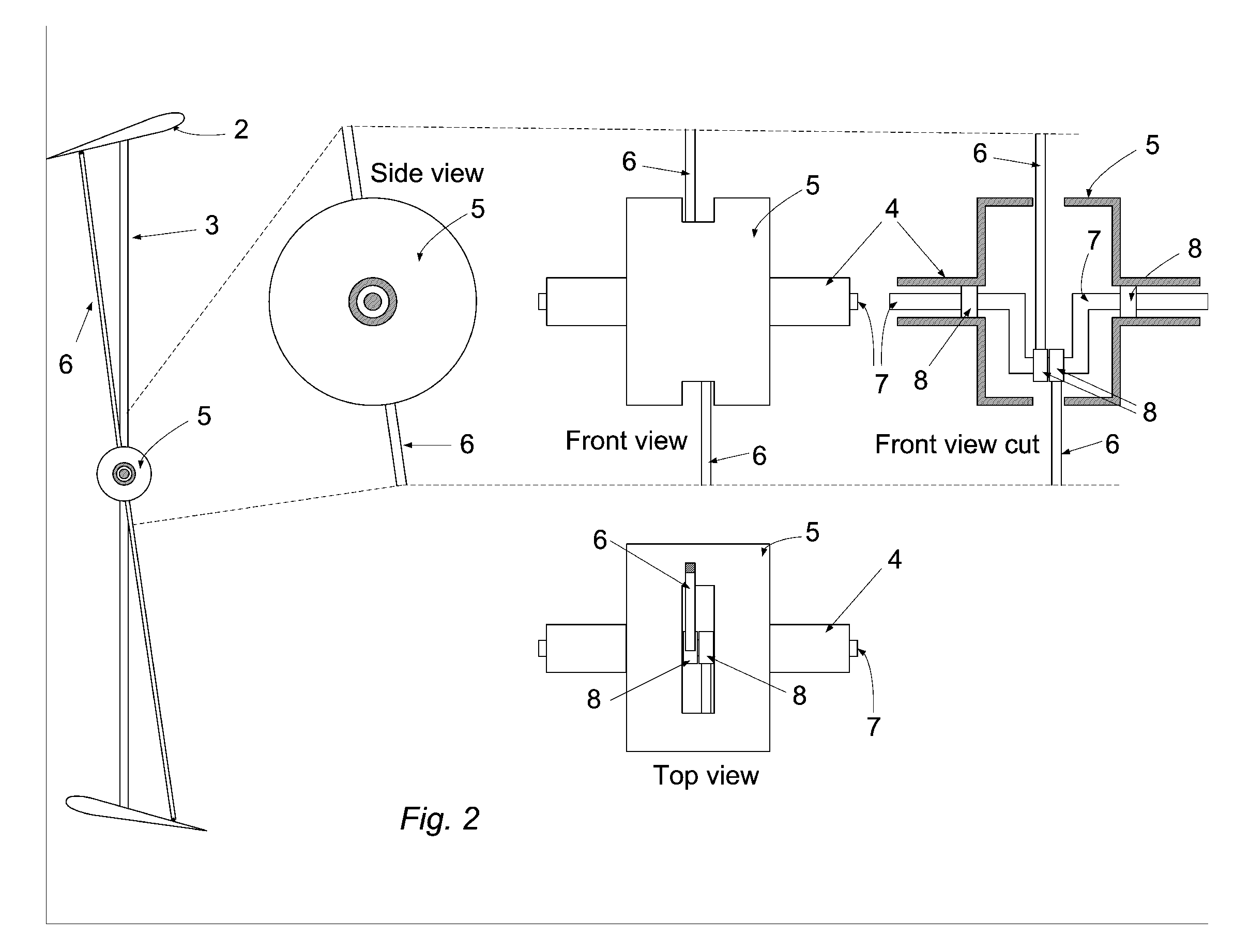
[0044] A crank handle drum 5 located at the center of axle 4 houses a crank handle 7. Turbine axle 4, supported by bearings 8, rotates around stationary a crank handle 7 as illustrated in FIG. 2 for a two-bladed turbine.

[0045] Crank arm 6 connects crank handle 7 to an articulated joint (not shown) located at the mid-rear section of blade 2. As the turbine rotates the crank handle 7 changes the blade pitch angle through crank arm 6.

[0046] The turbine axle 4 drives a pair of power generators 9. Generator 9 comprises a gear box (not shown) and an electrical generator (not shown).

[0047] Turbine frame 10 supports the power generators 9 and is airlifted by blimp 11.

[0048] Blimp 11 airlifts turbine frame 10 by ...


PUM


Abstract

A hovering wind turbine (1) whose blades (2) lie on the surface of an imaginary horizontal cylinder and have their pitch angle changing as a function of the rotational angle, allowing them to gather wind energy mainly in the upwind and downwind sectors of the cylindrical path and to use a fraction of the gathered energy to create lift by deflecting air downwards, mainly in the upper and lower sectors of the cylindrical path. The remainder of the gathered wind energy is used to drive a pair of on board electrical power generators (9), and anchoring tethers (13) carry electrical current to a land of offshore site. The turbine (1) is tied to a blimp (11) that is purposely located in its wind shade and keeps it airborne during periods of light or no wind.

Description

CROSS-REFERENCE TO RELATED APPLICATIONS [0001] This application claims the benefit of PPA Ser. No. 60 / 481,880, filed 2004-01-10 by the present inventor.BACKGROUND OF INVENTION [0002] 1. Field of Invention [0003] This invention relates to tethered wind turbines capable of gathering wind energy while airborne anchored to a land or offshore site. [0004] 2. Prior Art [0005] A prior art device is disclosed in U.S. Pat. No. 4,491,739 by Watson where a horizontal axis tethered wind turbine is mounted around the body of a blimp. It relies solely in the buoyant lift of the blimp to offset the vertical component of tether's anchoring force. A very large blimp is required for this task. [0006] Another prior art device is disclosed in U.S. Pat. No. 4,659,940 by Shepard. He proposes that a number of airfoils be connected to wheel rims to rotate according to a cylindrical path. A kitecraft secured to an anchoring tether supports the cylindrical structure. Shepard did not consider using the airfoi...

Claims


Application Information

Patent Timeline
Patent Type & Authority Applications(United States)
IPC IPC(8): F03D9/00H02P9/04F03D3/00F03D3/06F03D11/04
CPCF03D3/002F03D3/065F03D3/068F03D11/04F05B2240/40F05B2240/92F05B2240/922F05B2240/923Y02E10/728Y02E10/74F03D13/20F03D9/25F03D13/25F03D3/062
Inventor MACEDO, ALEANDRO SOARES
Owner MACEDO ALEANDRO SOARES
Learn More