Display apparatus and display method

Inactive Publication Date: 2006-05-04
CANON KK
View PDF2 Cites 7 Cited by
  • Summary
  • Abstract
  • Description
  • Claims
  • Application Information

AI Technical Summary

Benefits of technology

[0011] The present invention is directed to a display apparatus allowing an operator to simply, easily, and quickly adjust displacement of its display panel.
[0014] As described above, according to the present invention, since position-adjusting-images of a plurality of colors formed in a plurality of different patterns are displayed and any of the patterns is selected, an image is compensated for in accordance with the selected adjusting image and is displayed, thereby achieving a display apparatus in which deterioration in image quality caused by relative displacement of panels is prevented with easier adjustment.
[0016] Also, according to the present invention, at least two of the adjusting images are arranged on opposing corners of the display frame, thereby achieving a display apparatus in which deterioration in image quality caused by relative rotational displacement of panels is prevented with easier adjustment.
[0020] Further, according to the present invention, since a rotational angle is computed on the basis of the at least two selected patterns displayed on the display frame and a display image is compensated by rotation and displayed, the rotational angle is easily computed, thereby achieving a display apparatus preventing deterioration in image quality with easier adjustment even when a display panel is rotationally displaced.

Problems solved by technology

While these methods are suitable for adjustment to be performed, for example, upon factory shipment (upon production), or by a service person (upon repair), unfortunately, an operator has difficulty in implementing them.
While displacement of the display position in the X and Y directions can be mechanically compensated for while looking at the corresponding display image, rotational displacement of the display cannot be manually corrected since two parameters of its rotational angle and rotation center must be adjusted at the same time.
While being possible in the X and Y directions, the adjustment by changing a drive timing is impossible in the rotational direction.
As a result, mechanical alignment of the positions of R, G, and B panels upon synthesizing their display images is difficult.
Also, displacement of the fixed position of the display panel due to change over time after shipment sometimes causes its display position to be displaced.

Method used


Image

  • Display apparatus and display method
  • Display apparatus and display method
  • Display apparatus and display method

Examples


Embodiment Construction

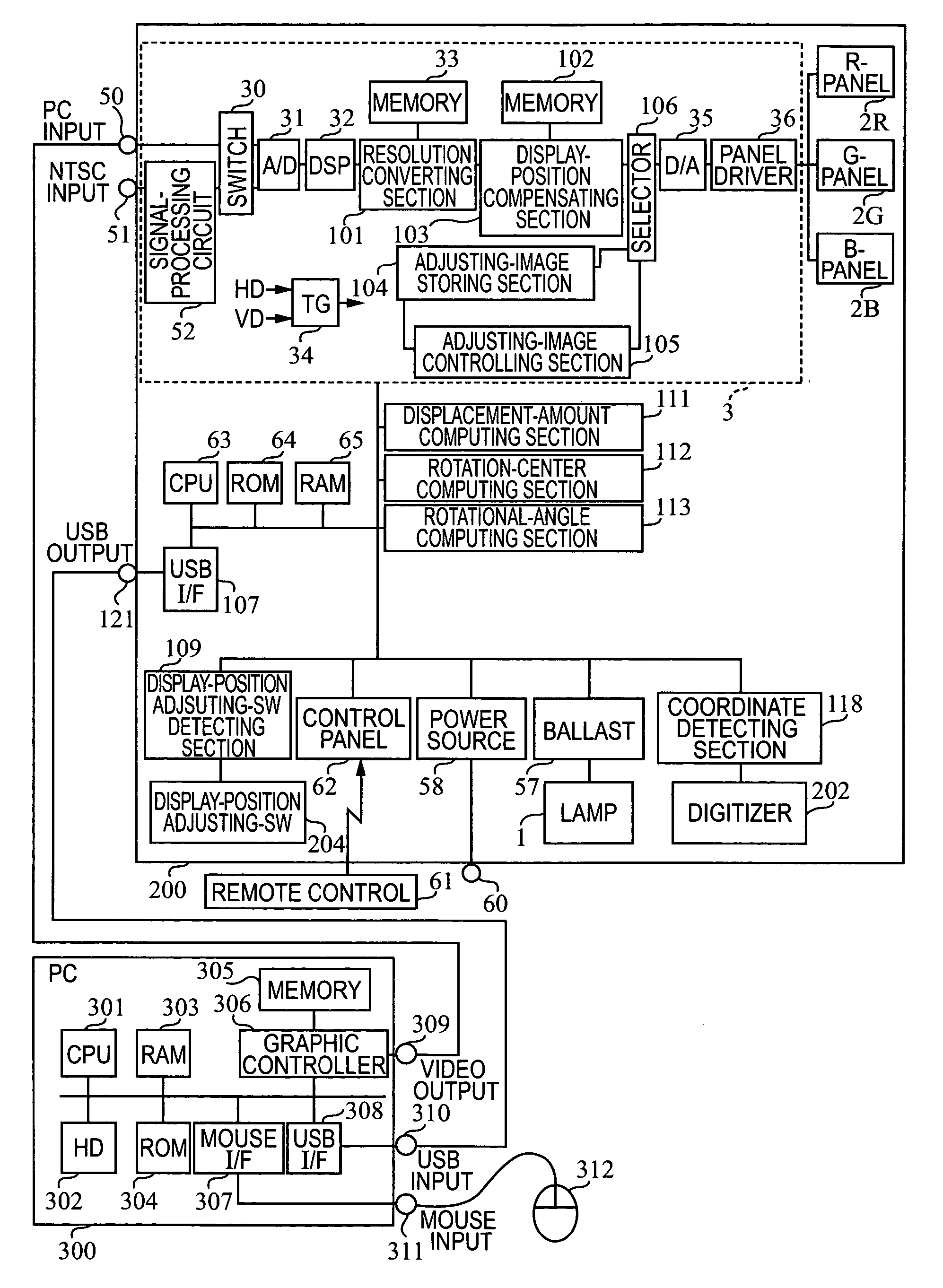
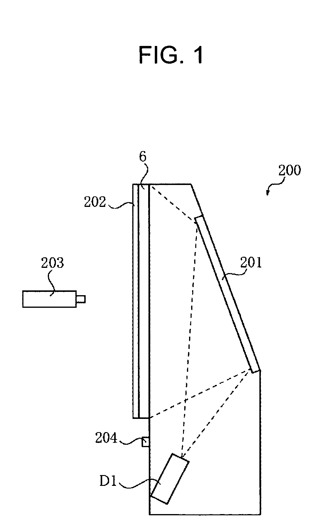
[0036]FIG. 1 is a side view of a rear-projection display apparatus 200 according to a first embodiment of the present invention.

[0037] An image projected from a projection display engine D1 is reflected at a reflective mirror 201 and projected onto a screen 6 from its rear surface. The screen 6 has a digitizer 202 fixed in front thereof, and position coordinates inputted from the front surface of the screen 6 with a digitizer pen 203 is inputted into the display apparatus 200. Any one of a variety of types including an optical type, a pressure sensitive type, and an ultrasonic type can be used as the digitizer.

[0038] A display-position adjusting SW 204 is used for instructing start of aligning adjustment.

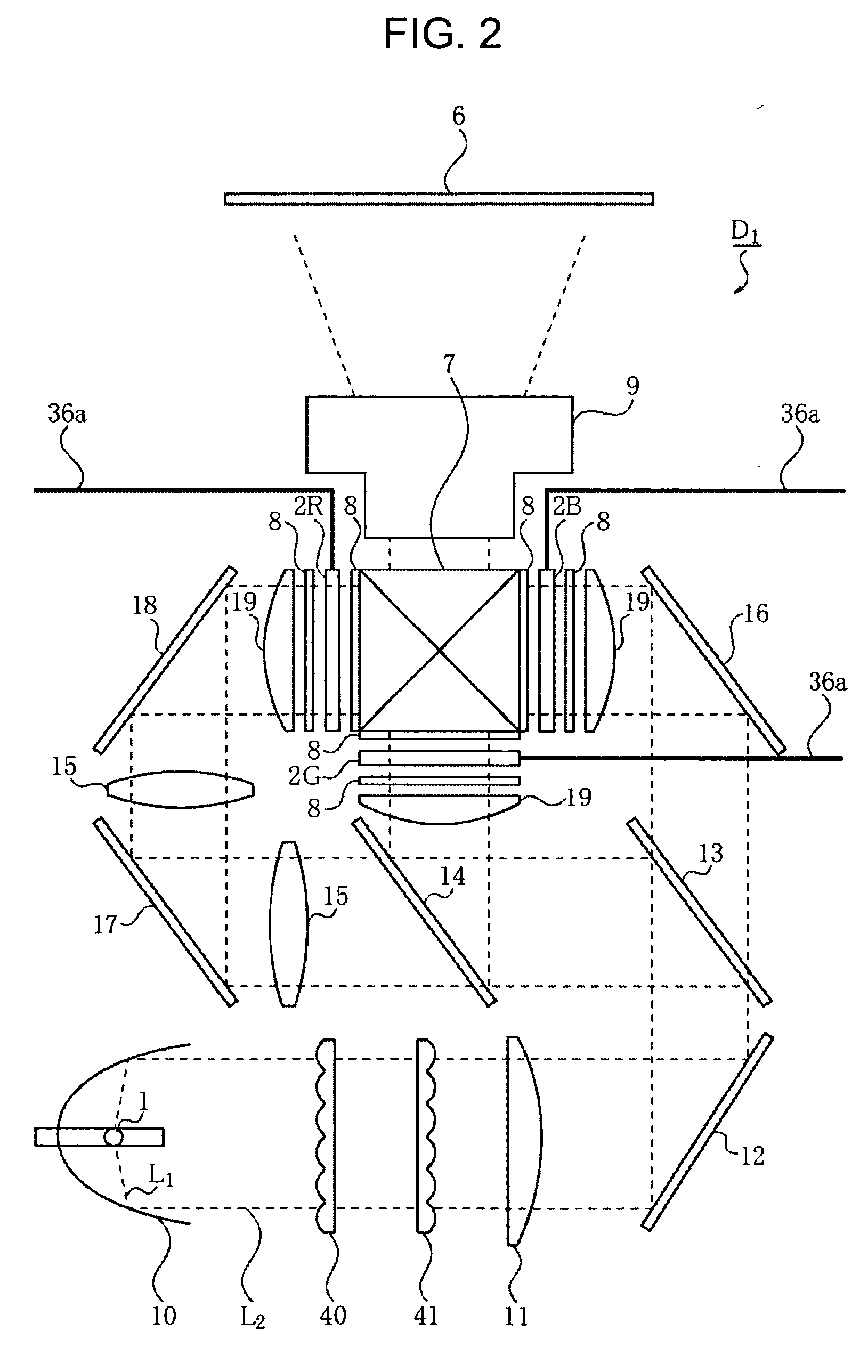
[0039] As shown in FIG. 2, the projection display engine D1 includes three liquid crystal panels 2R, 2G, and 2B corresponding to respective red (R), green (G), and blue (B) display colors so as to serve as optical modulating devices, and each of these three liquid crystal panels ...


PUM


Abstract

A three-panel projection apparatus in which display quality due to displacements of fixing positions of panels is improved is provided. By displaying position-adjusting-images of a plurality of colors formed in a plurality of different patterns and by selecting any of the patterns, the overall display frame is compensated for with a method corresponding to the selected adjusting images and displayed. Further, at least two of the adjusting images are arranged on the opposing corners of the display frame. Still further, the compensating method performs computation on the basis of a target pixel and its circumferential pixels so as to form a compensation pixel.

Description

BACKGROUND OF THE INVENTION [0001] 1. Field of the Invention [0002] The present invention relates to a display apparatus, and more particularly, it relates to a display apparatus synthesizing images displayed on a plurality of display devices and displaying the synthesized one. [0003] 2. Description of the Related Art [0004] In a known method for adjusting a display position, a panel and the like are mechanically moved (e.g., see Japanese Patent Laid-Open No. 7-59037, corresponding to U.S. Pat. No. 5,592,239). [0005] Also, in a known electrical method for adjusting the display position, the display position in the X and Y directions is adjusted, for example, by changing a drive timing of the panel. [0006] While these methods are suitable for adjustment to be performed, for example, upon factory shipment (upon production), or by a service person (upon repair), unfortunately, an operator has difficulty in implementing them. [0007] While displacement of the display position in the X an...

Claims


Application Information

Patent Timeline
IPC IPC(8): G09G5/00H04N3/26
CPCG09G3/002G09G2320/02G09G2340/0464H04N9/3182H04N9/3185
Inventor SAKASHITA, YUKIHIKO
Owner CANON KK
Why Eureka
Try Eureka