Light emitting diode driving device and optical transmission device including the same

Active Publication Date: 2006-05-04
SHARP KK
View PDF8 Cites 12 Cited by
  • Summary
  • Abstract
  • Description
  • Claims
  • Application Information

AI Technical Summary

Benefits of technology

[0013] The present invention was made in view of the above conventional problems, and an object of the present invention is to provide a light emitting diode driving device which can carry out high-speed driving by realizing faster rising and falling of a light output waveform and realizing the light output waveform having less overshoot by improving a response characteristic, etc. with respect to a temperature change, and an optical transmission device including the light emitting diode driving device.
[0016] As a result, when the light emitting diode emits light, the peaking current, which is added when the light emitting diode emits light and does not emit light, is controlled so as not to excessively generate the overshoot in the light output waveform. Meanwhile, when the light emitting diode does not emit light, the peaking current is controlled so as not to excessively generate backshoot. With this, it is possible to appropriately discharge the electric charge from the parasitic capacitor of the light emitting diode, suppress excess reduction of the fall time in the light output waveform, and reduce the fall time to obtain the required fall time of the light output waveform.
[0017] In this way, it is possible to obtain the light output waveform of the light emitting diode, the light output waveform having fast rise time and fall time without generating the overshoot.
[0018] Therefore, it is possible to provide the light emitting diode driving device which realizes the high-speed driving by speeding up the rising and falling of the light output waveform, improving the response characteristic, etc. with respect to the temperature change and realizing the light output waveform having less overshoot.
[0020] According to the above invention, it is possible to carry out the optical fiber communication, the space light transmission communication and the photocoupler signal transmission at low cost with a simple circuit configuration. In addition, it is possible to realize the light output waveform having the fast rising and falling and having less overshoot by improving the response characteristic, etc. with respect to the temperature change. In this way, it is possible to provide the optical transmission device including the light emitting diode driving device which can realize the high-speed driving.

Problems solved by technology

The semiconductor laser can carry out high-speed driving easily, but becomes unstable depending on temperatures.
Therefore, in order to stabilize thermal operations, various devisals become necessary and a circuit configuration becomes complicated.
However, the quartz fiber is weak in bending, needs to be handled carefully, and is expensive.
Therefore, there are problems in that, as shown in FIG. 11(c), an adequately fast response cannot be obtained because the peaking current Ipeak becomes inadequate at high temperature.
However, the conventional method cannot arbitrarily adjust the peaking current Ipeak in proportion to the driving current Idriv.
Thus, in the case in which the overshoot of the light is large, a large error occurs in the light signal level, and deterioration of receiving sensitivity occurs.

Method used


Image

  • Light emitting diode driving device and optical transmission device including the same
  • Light emitting diode driving device and optical transmission device including the same
  • Light emitting diode driving device and optical transmission device including the same

Examples


Embodiment Construction

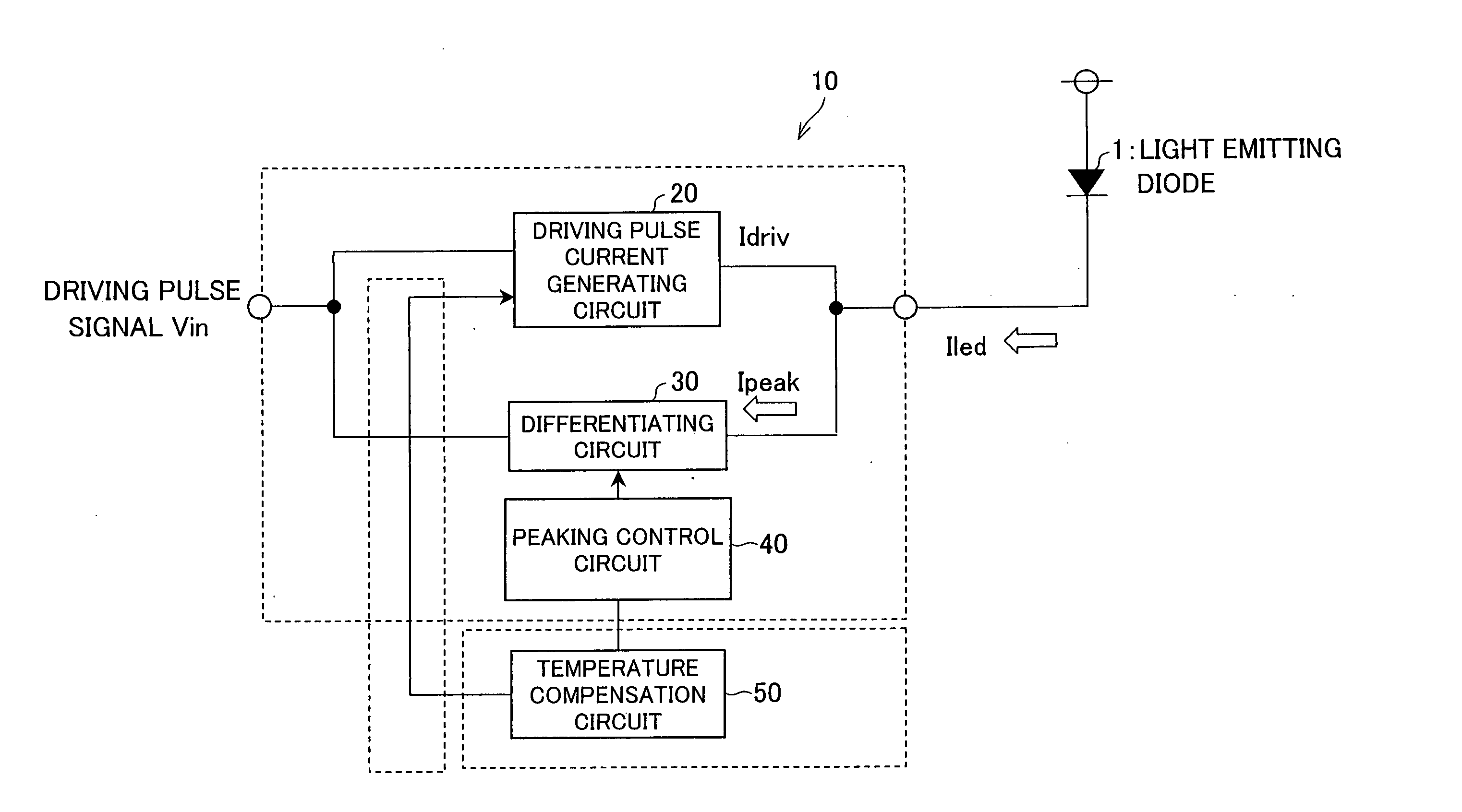
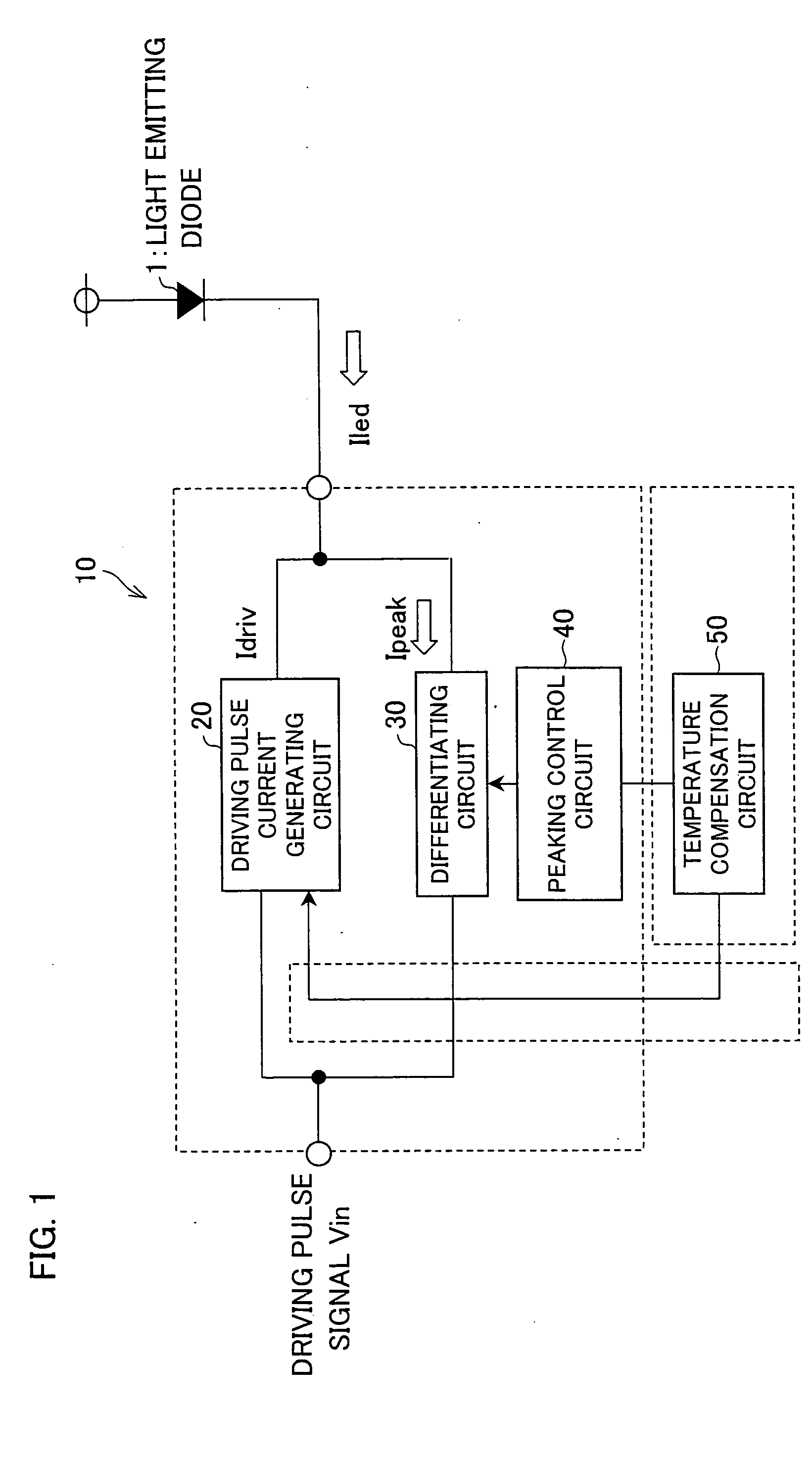
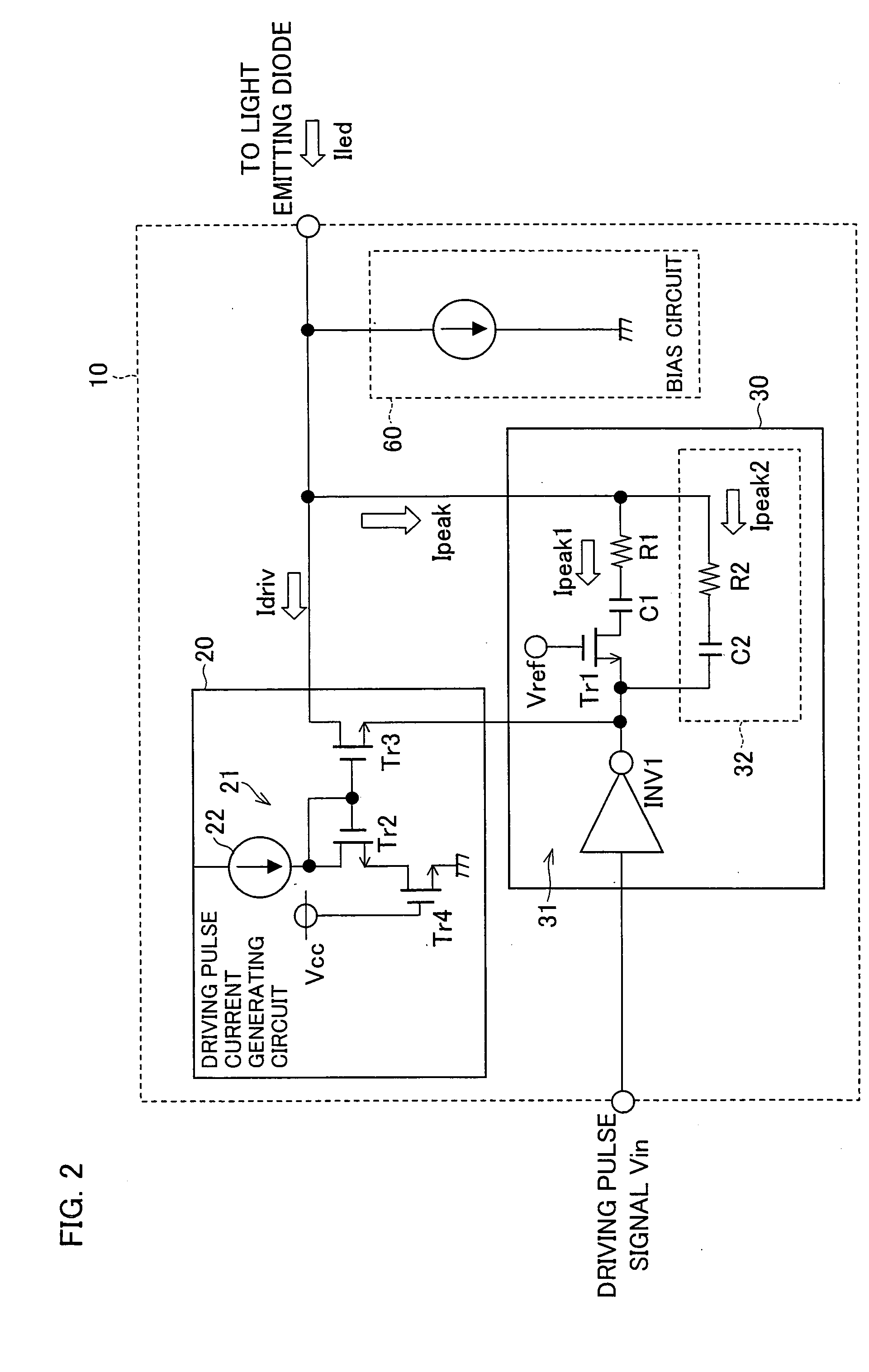
[0040] The following explains one embodiment of the present invention in reference to FIGS. 1 to 8. Note that a light emitting diode driving device of the present embodiment is applicable to an optical transmission device which uses the light emitting diode driving device as or as part of a driving circuit of a semiconductor light emitting element for an optical fiber communication, for a space light transmission communication or for a photocoupler signal transmission.

[0041] The optical transmission device of the present embodiment is a communication device which carries out a control signal transmission and a data transmission between devices, and is an optical transmission device which carries out the data transmission using light to electrically insulate the devices. The optical transmission device includes (i) a light emitting element which converts an electric signal into a light signal, (ii) a light emitting diode driving device, (iii) a light receiving element (not shown) wh...


PUM


Abstract

A light emitting diode driving device for driving an LED includes (i) a driving pulse current generating circuit for generating a driving current for the LED in accordance with a driving pulse signal supplied from outside and (ii) a differentiating circuit for generating a peaking current obtained by differentiating the driving pulse signal. A current that is equal to the sum of the driving current and the peaking current flows to the LED. The light emitting diode driving device further includes a peaking control circuit for controlling the magnitude of the peaking current generated from the differentiating circuit.

Description

[0001] This Nonprovisional application claims priority under 35 U.S.C. § 119(a) on Patent Application No. 314341 / 2004 filed in Japan on Oct. 28, 2004, the entire contents of which are hereby incorporated by reference. FIELD OF THE INVENTION [0002] The present invention relates to a light emitting diode driving device and an optical transmission device including the light emitting diode, and is effective for a signal transmission using light in a wide range of operating temperatures. BACKGROUND OF THE INVENTION [0003] An optical communication of digital signals is widely used in recent years, and a light emitting diode (hereinafter referred to as an “LED”) and a semiconductor laser are widely used as a light source. The semiconductor laser can carry out high-speed driving easily, but becomes unstable depending on temperatures. Therefore, in order to stabilize thermal operations, various devisals become necessary and a circuit configuration becomes complicated. Meanwhile, by using the...

Claims


Application Information

Patent Timeline
IPC IPC(8): G09G3/14H01L33/00
CPCH04B10/502H04B10/508
Inventor MATSUDA, HIDEO
Owner SHARP KK
Why Eureka
Try Eureka