Ink jet recording apparatus

a recording apparatus and jet technology, applied in printing and other directions, can solve the problems of unresolved problems, scratches or unprinted lines of recorded images, increased ink density, and increased difficulty in achieving the effect of reducing drawbacks and shortening the time period

Inactive Publication Date: 2006-05-04
CANON KK
View PDF6 Cites 4 Cited by
  • Summary
  • Abstract
  • Description
  • Claims
  • Application Information

AI Technical Summary

Benefits of technology

[0014] The present invention is designed to solve the problems discussed above. It is an object of the invention to provide an ink jet recording apparatus capable of suppressing the drawback that may be brought about by the generation of mist, while attempting making the time of recording on a recording medium shorter.
[0018] In accordance with the present invention, the following effect is demonstrated:
[0019] The invention is so structured that based on the idea that the influence exerted by the mist generation is small when the number of preliminary discharges is small, the preliminary discharges are performed in the status of having the cap away, and based on the idea that the influence exerted by the mist generation is large when the number of preliminary discharges is large, the preliminary discharges are performed in the capping status. Thus, with the execution of preliminary discharges using plural modes of preliminary discharges corresponding to the status of the recording apparatus, it is made possible to provide an ink jet recording apparatus capable of suppressing the drawback resulting from the mist generation, while implementing the recording on a recording medium in a shorter period of time.

Problems solved by technology

On the other hand, however, there also exist problems yet to be solved.
As the problems of the ink jet recording method, the scratches or unprinted lines of recorded images and the increased density of ink may be encountered due to the evaporation of ink from discharge ports, or the various ink colors may intermix in the discharge ports after the execution of the suction recovery operation, among some other causes.
However, it is known that when preliminary discharges are performed, there tends to occur the phenomenon that there are floating in the apparatus the fine ink droplets that accompany ink droplets discharged or the fine ink droplets generated by part of rebounded ink droplets which are landed onto the cap, or, further, the discharged ink droplets themselves, which makes flying speed slower before the droplets are impacted, due to the influence of air resistance or the like.
The ink droplets and others that float in the apparatus are collectively called “mist”, and if there is the floating of a considerable amount of mist, the adhesion thereof occurs on the components in the apparatus, leading to various kinds of drawbacks eventually.
If a considerable amount of mist adheres to the parts, which are in contact with a recording medium, the recording medium is stained, and if the surface thereof is stained, it results even in the degradation of recording quality.
Also, if a considerable amount of mist adheres to the parts, such as an optical sensor, it becomes impossible to carry out exact detection, leading to the operational drawback, and the degradation of recording quality may ensue or the recording apparatus is caused to be out of order in some cases.
Also, if a considerable amount of mist adheres to the parts that the user may handle, his hand may be stained unavoidably.
Nevertheless, although it becomes possible to suppress the mist generation by the performance of preliminary discharges in the status where the discharge port surface is capped, there is a problem that the time of recording on a recording medium takes more time, because it requires a time to execute the capping operation to enable the cap to be in contact with the discharge port surface.

Method used


Image

  • Ink jet recording apparatus
  • Ink jet recording apparatus
  • Ink jet recording apparatus

Examples


first embodiment

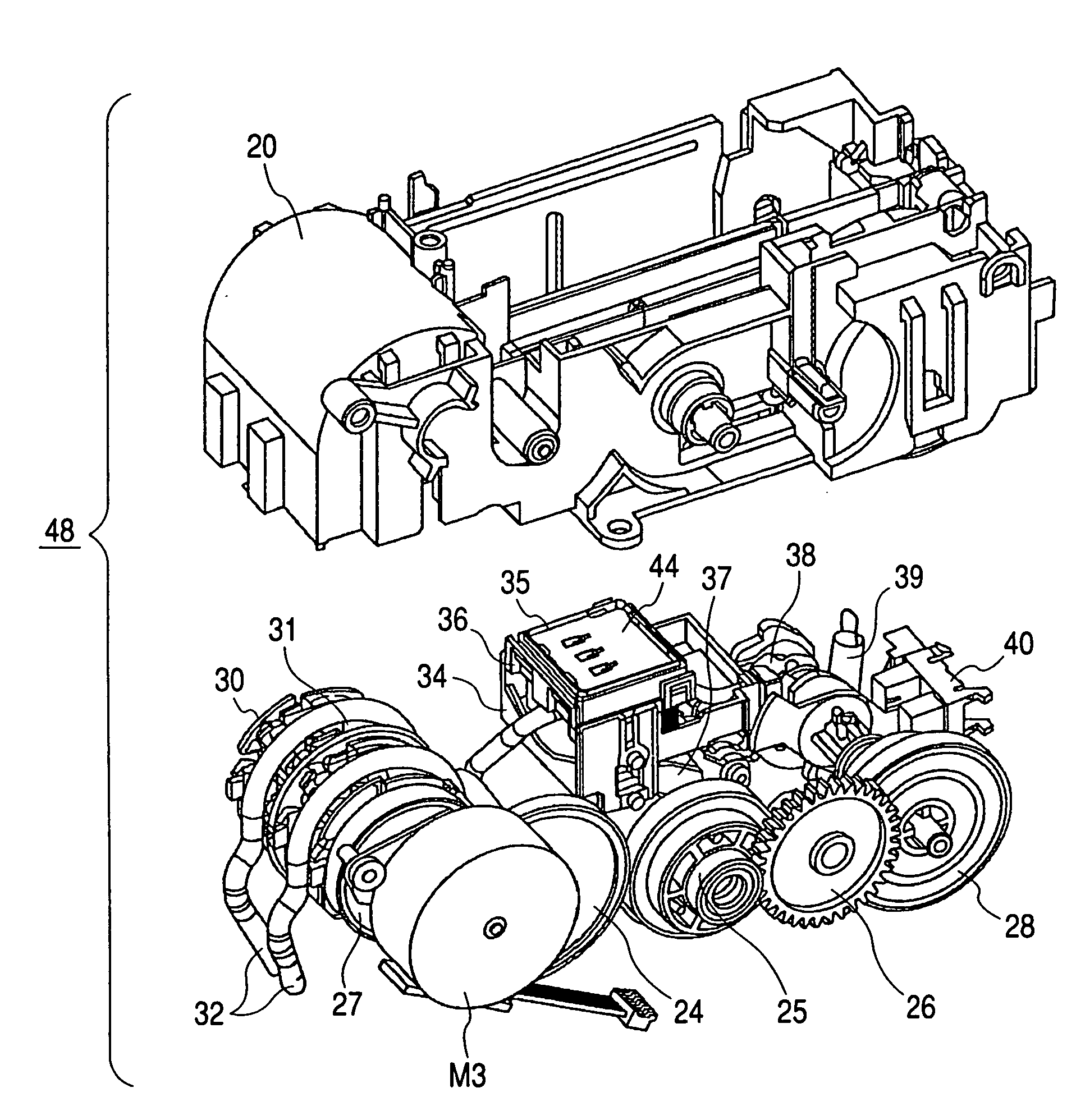
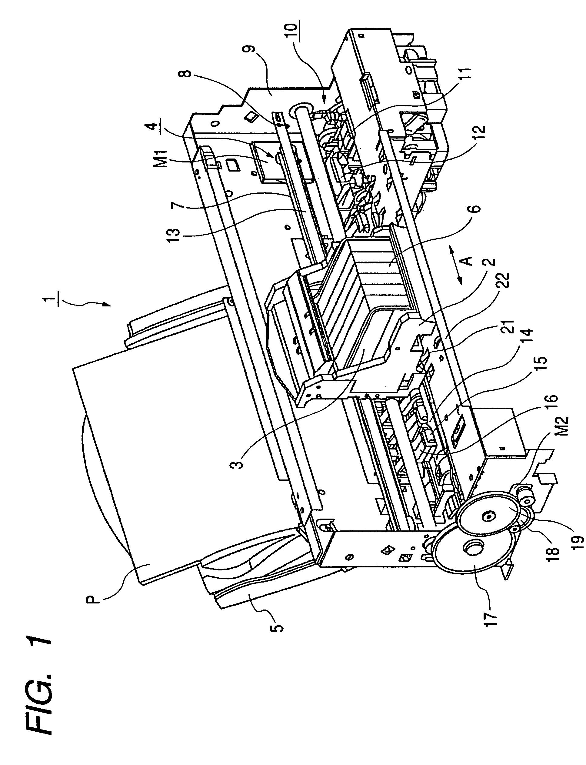
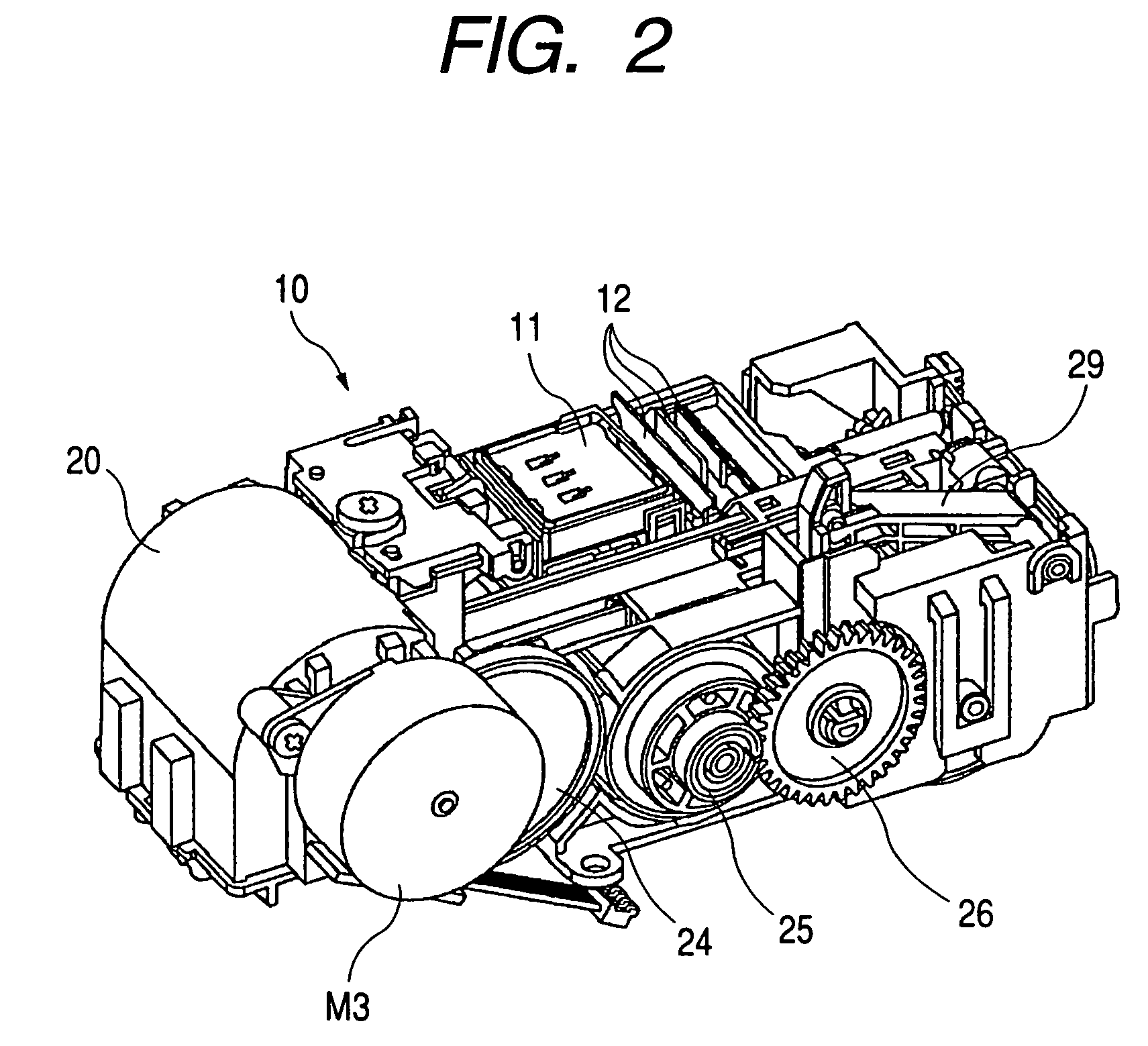
[0036] Hereinafter, with reference to the accompanying drawings, a first embodiment will be described in accordance with the present invention. In this respect, the same reference marks are applied to the same or corresponding parts throughout each of the drawings. FIG. 1 is a perspective view that schematically shows the inner side of an ink jet recording apparatus provided with a discharge recovery device. FIG. 2 is a perspective view that schematically shows the discharge recovery device of the ink jet recording apparatus represented in FIG. 1. FIG. 3 is an exploded perspective view that schematically shows the inner structure of the discharge recovery device of the ink jet recording apparatus of the present invention (the ink jet recording apparatus represented in FIG. 1).

[0037] In FIG. 1 to FIG. 3, the ink jet recording apparatus 1 is provided with a driving motor M serving as the driving source; a carriage 2 having the ink jet recording head 3 mounted thereon; a power transmi...

second embodiment

[0069]FIG. 7 is a table of the preliminary discharge operations of an ink jet recording apparatus in accordance with a second embodiment of the present invention. What differs from the first embodiment is that the preliminary discharges A2 and A3 do not perform the preliminary discharges in the cap away from the discharge port surface, but perform them in the cap in the capping status.

[0070] The present embodiment is characterized to make the arrangement for increasing the mode in which the preliminary discharges are made in the cap in the capping status where the cap is in contact, in addition to the preliminary discharge D, so as to suppress the generation of mist more than the first embodiment.

[0071]FIG. 9 is a view that shows the operational sequence when preliminary discharges are made in accordance with the present embodiment.

[0072] In step S50, a preliminary discharge execution command is issued. Then, it is determined whether the mode of the preliminary discharges is such...


PUM


Abstract

An ink jet recording apparatus is structured to perform discharges in the capping status when preliminary discharges are performed in a shot number larger than a predetermined number, and perform discharges in a cap or a preparatory port other than the cap when the preliminary discharges are performed in a shot number less than the predetermined number. With the structure thus arranged, it is made possible to implement the suppression of the mist generation due to the preliminary discharges, and to make the time of recording on a recording medium shorter as well.

Description

[0001] This application is a divisional of application Ser. No. 10 / 648,300, filed Aug. 23, 2005, the entire content of which is incorporated herein by reference.BACKGROUND OF THE INVENTION [0002] 1. Field of the Invention [0003] The present invention relates to an ink jet recording apparatus that performs recording by discharging ink from recording means to a recording medium. [0004] 2. Related Background Art [0005] Conventionally, the recording apparatus that records on a recording medium, such as paper, cloth, plastic sheet, or OHP sheet, among some other materials (hereinafter, also, simply referred to as a “recording sheet”) has been proposed in a mode in which a recording head of wire-dot method, thermal sensitive method, thermal transfer method, ink jet method, or the like is made mountable thereon, for example. [0006] Of such recording apparatuses, the one that adopts an ink jet recording method for recording on a recording sheet by discharging ink from the ink discharge port...

Claims


Application Information

Patent Timeline
Patent Type & Authority Applications(United States)
IPC IPC(8): B41J2/165B41J2/175B41J2/18B41J2/185
CPCB41J2/16526
Inventor YAZAWA, TAKESHITAJIKA, HIROSHIKONNO, YUJIIDE, DAISAKUMASUYAMA, ATSUHIKOMARU, AKIKOYOSHIKAWA, HIROKAZU
Owner CANON KK
Why Eureka
Try Eureka