Eureka AIR delivers breakthrough ideas for toughest innovation challenges, trusted by R&D personnel around the world.

Phase difference control component, process for producing the same and liquid crystal display device

a phase difference and control component technology, applied in the direction of optics, instruments, optical elements, etc., can solve the problems of small visibility angle, inability to properly display, and leakage of light from pixels, and achieve excellent symmetry of visibility angle, the effect of increasing the visibility angle of liquid crystal display devices and achieving the effect of high phase difference symmetry

Inactive Publication Date: 2006-05-04
DAI NIPPON PRINTING CO LTD
View PDF7 Cites 6 Cited by
  • Summary
  • Abstract
  • Description
  • Claims
  • Application Information

AI Technical Summary

Benefits of technology

[0016] Accordingly, an object of the present invention is to provide a phase difference control component, which has excellent phase difference symmetry and is optically compensable, capable of realizing a liquid crystal display device having a wide angle of visibility, and a process for producing the same.
[0024] In the phase difference control component according to the present invention, any pretilt angle does not exist in the liquid crystal molecules constituting the phase difference member. Therefore, the level of the phase difference symmetry is so high that the angle of visibility of the liquid crystal display device can be effectively increased. Further, a liquid crystal display device, which is excellent in symmetry of the angle of visibility, can be realized.
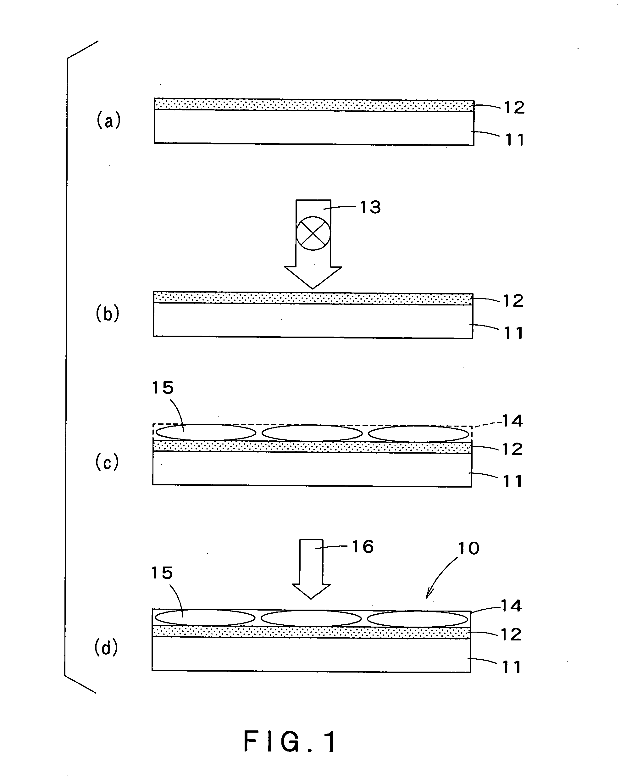
[0025] Further, in the process according to the present invention, in constructing a phase difference control component using a liquid crystal material, a phase difference layer having a pretilt angle of substantially 0 degree can be formed by using a photoalignment method and applying ultraviolet light in the vertical direction. Therefore, when the level of phase difference is measured by varying the observation angle in the slow phase axis direction, highly symmetrical phase difference control can be realized and, thus, a phase difference control component which can realize higher-accuracy optical compensation can be provided.
[0026] Further, according to the present invention, when the phase difference control component is stacked directly on a color filter, a higher-performance phase difference control component free from shrinkage with the elapse of time and peel-off which are problems of the conventional film-type phase difference control component can be provided.

Problems solved by technology

A small angle of visibility is a problem inherent in LCDs.
This problem is caused by light leakage from pixels, which should originally display black, when LCDs are viewed in an oblique direction.
Due to this light leakage, the inversion of contrast takes place, and proper display becomes impossible.
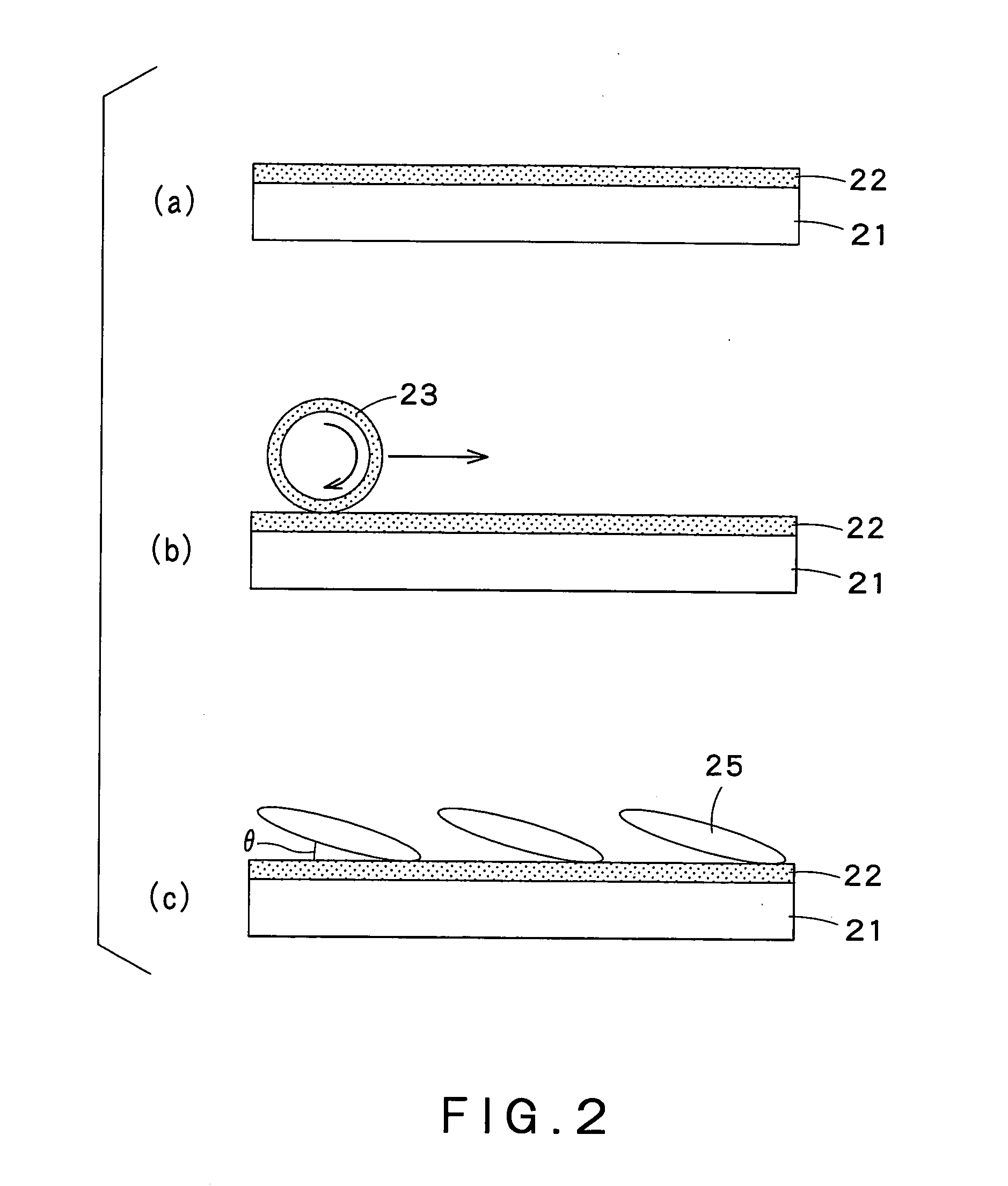
For this reason, a liquid crystal display device to which a phase difference control component formed of a liquid crystal material with a pretilt angle θ has been applied, suffers from a problem that, except for a change in observation angle in the phase advance axis, display images are different.
Since the pretilt angle also propagates in the thickness-wise direction of the film, when the phase difference layer comprises a plurality of liquid crystal layers stacked on top of each other, the alignment at the interface of the liquid crystal layers is adversely affected.
In large-size liquid crystal televisions, due to properties of angle of visibility within a display face attributable to the large area, the symmetry of the angle of visibility poses a severe problem.

Method used


Image

  • Phase difference control component, process for producing the same and liquid crystal display device
  • Phase difference control component, process for producing the same and liquid crystal display device
  • Phase difference control component, process for producing the same and liquid crystal display device

Examples


examples

[0063] The following Examples further illustrate the present invention. However, it should be noted that the present invention is not limited to these Example.

1. Preparation of Base Material With Aligning Film

[0064] A glass substrate (1737 glass, manufactured by Corning Inc.) which had been cleaned by a predetermined method was provided as a base material, and AL 1254 (manufactured by JSR Corporation) was provided as an aligning film material. The aligning film material was coated by flexographic printing onto the glass substrate to form a 600 angstrom-thick aligning film.

[0065] Next, polarized ultraviolet light was applied to the aligning film at 5 J / cm2 in a direction vertical to the base material to form an aligning film by a photoalignment method to which monoaxial anisotropy had been imparted.

[0066] For comparison, a base material provided with an aligning film subjected to the conventional rubbing treatment was prepared.

2. Preparation of Ink for Phase Difference Control...


PUM

PropertyMeasurementUnit
pretilt angleaaaaaaaaaa
thicknessaaaaaaaaaa
phase differenceaaaaaaaaaa

Abstract

There are provided a phase difference control component, which can realize a liquid crystal display device having a wide angle of visibility, has excellent phase difference symmetry and can realize optical compensation, and a process for producing the same. The phase difference control component comprises a base material; and a phase difference control layer formed of a fixed liquid crystal material provided on the base material through an aligning film and is characterized in that the angle of liquid crystal molecules, present at the interface of the aligning film and the phase difference control layer, to the base material being substantially 0 (zero) degree.

Description

BACKGROUND OF THE INVENTION [0001] 1. Field of the Invention [0002] The present invention relates to a phase difference control component comprising a liquid crystal material, which has excellent symmetry with respect to the angle of visibility and is optically compensable, and a process for producing the same, and a liquid crystal display device comprising said phase difference control component. [0003] 2. Background Art [0004] Color liquid crystal displays (hereinafter often referred to as “LCDs”) have features such as thin shape, light weight, low power consumption, and flickerless, and the market of color liquid crystal displays for PCs including notebook computers has been rapidly grown. In recent years, regarding displays for PCs, there is an increasing demand for desktop monitors which are larger in size than notebook computers. Further, LCDs have become utilized in PCs, as well as in TVs for which CRTs have hitherto been mainly utilized. [0005] A small angle of visibility is...

Claims


Application Information

Patent Timeline
Patent Type & Authority Applications(United States)
IPC IPC(8): G02F1/1335
CPCG02B5/3016G02F1/13363G02F2001/133633C09K2323/00C09K2323/02C09K2323/03G02F1/133633G02F1/133711G02F1/133788G02F1/133749
Inventor MORIYA, NORIHISAIKEGAMI, KANAMI
Owner DAI NIPPON PRINTING CO LTD
Why Eureka
Eureka Blog
Learn More