Transparent substrate, electro-optical device, image forming device, and method for manufacturing electro-optical device

a technology of transparent substrate and electrooptical device, which is applied in the direction of instruments, lenses, electrographic processes, etc., can solve the problems of reducing sacrificing the productivity of organic el exposure head, and sacrificing so as to maintain the efficiency of using light and improve the productivity of micro lens

Inactive Publication Date: 2006-05-04
SEIKO EPSON CORP
View PDF1 Cites 14 Cited by
  • Summary
  • Abstract
  • Description
  • Claims
  • Application Information

AI Technical Summary

Benefits of technology

[0009] An advantage of the invention is to provide a transparent substrate, an electro-optical device, and an image forming device that are equipped with a micro lens having high productivity while maintaining an efficiency of using light, and to provide a method for manufacturing the electro-optical device.
[0010] A transparent substrate according to a first aspect of the invention includes a micro lens. Light entered a side of a light incident surface of the transparent substrate is emitted from the micro lens formed on a side of a light taking-out surface of the transparent substrate. The micro lens is provided in a groove concaved from the light taking-out surface, and is provided with an optical surface continuing in one direction.
[0011] According to the transparent substrate, the tolerance of the position for forming and allocating the micro lens can be expanded in the one direction by the optical surface, which is included in the micro lens, continuing in the one direction. As a result, the productivity of the micro lens, and thus the productivity of the transparent substrate can be improved. In addition, the micro lens can be formed adjacent to the light incident surface by the depth of the groove, allowing an opening angle of the micro lens with respect to the light incident surface to be increased. Therefore, the loss in the efficiency of using light irradiated on the surface including the one direction can be compensated with the efficiency of using light irradiated on the surface perpendicular to the one direction by forming the groove. As a result, the productivity of the transparent substrate, which maintains the efficiency of using light, can be improved.
[0012] In the transparent substrate, the one direction is a direction in which the groove is formed, and the micro lens is a half-cylindrical convex lens having the optical surface in the one direction.
[0013] According to the transparent substrate, the productivity of the transparent substrate can be improved while maintaining the efficiency of using light of the transparent substrate by forming the half-cylindrical convex lens having the optical surface in the direction in which the groove is formed.
[0014] In the transparent substrate, the one direction is the direction in which the groove is formed. The micro lens is a half-cylindrical group convex lens including the half-cylindrical convex lens having the optical surface perpendicular to the one direction, and the half-cylindrical convex lens is provided in the one direction.

Problems solved by technology

These constraints cause a problem of sacrificing the productivity of the organic EL exposure head.
However, in the second example of related art, the micro lens is formed by discharging a liquid into a circular hole having nearly the same size of the organic EL element, resulting in the following problems.
The displacement results in variations in an opening diameter of micro lens or in refractive index, etc., causing a problem of sacrificing the productivity of the micro lens, and thus the productivity of the organic EL exposure head.
The enlarged hole, however, causes the displacement of the micro lens, arising the problem in that the efficiency of using light is lowered.

Method used


Image

  • Transparent substrate, electro-optical device, image forming device, and method for manufacturing electro-optical device
  • Transparent substrate, electro-optical device, image forming device, and method for manufacturing electro-optical device
  • Transparent substrate, electro-optical device, image forming device, and method for manufacturing electro-optical device

Examples


first embodiment

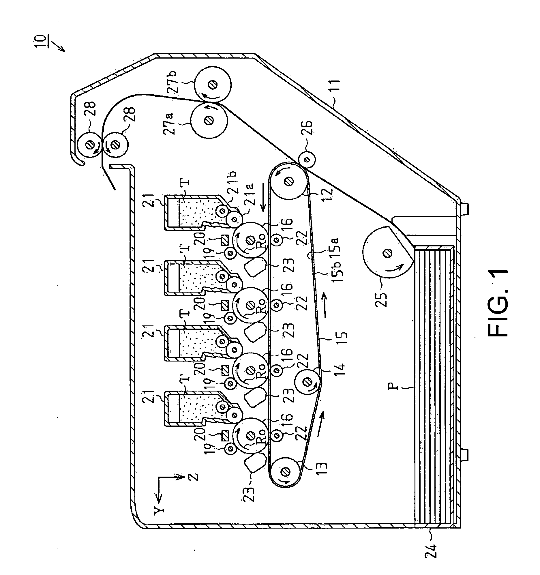
[0048] As shown in FIG. 1, an electrophotographic printer 10 (hereinafter, simply referred to as the printer 10) is provided with a chassis 11 formed in a box shape. Inside the chassis 11, a driver roller 12, a driven roller 13, and a tension roller 14 are provided. In addition, an intermediate transfer belt 15, which serves as a transfer medium, is stretched with respect to each of the rollers 12 to 14. The intermediate transfer belt 15 is circularly driven by the rotation of the driver roller 12 in the direction indicated by the arrow in FIG. 1.

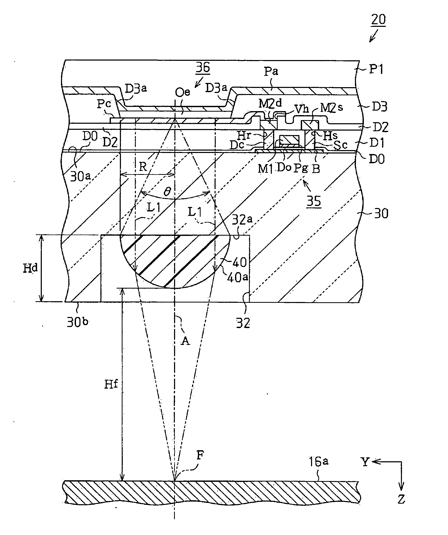
[0049] Above the intermediate transfer belt 15, four (4) photosensitive drums 16, which serve as an image carrier, are rotatably provided side-by-side in the stretched direction of the intermediate transfer belt 15 (in a sub scanning direction Y). On the outer circumferential surface of the photosensitive drum 16, a photosensitive layer 16a (refer to FIG. 4) having photoconductivity is formed. The photosensitive layer 16a is charged with p...

second embodiment

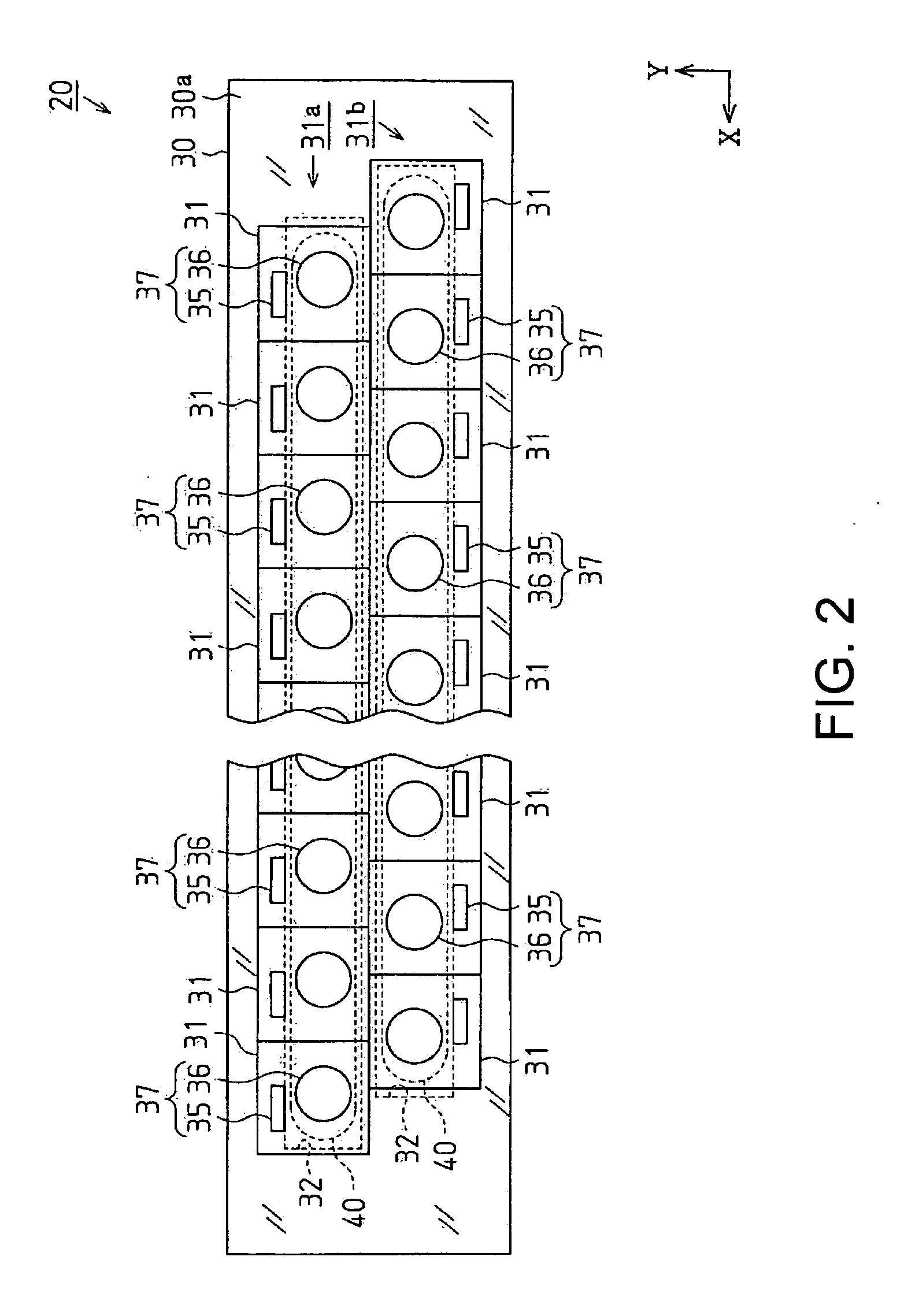
[0102] Next, a second embodiment of the invention will be explained with reference to FIGS. 8 to 11. Here, in the second embodiment differs from the first embodiment in that the shape of the micro lens and the manufacturing method are changed. Other than these, the second embodiment has the same structure of the first embodiment. Therefore, the shape of the micro lens and the manufacturing method will be minutely explained below. FIGS. 8 to 10 are a plan view of the exposure head 20 seen from the surface 30a for forming a light-emitting element, a plan view of the exposure head 20 seen from the surface 30b for taking out light, and a front sectional-view of the exposure head 20. FIG. 11 shows a process of the exposure head 20.

[0103] As shown in FIGS. 9 and 10, a micro lens 50 is formed on the groove bottom 32a of the groove 32. The micro lens 50 is a half-cylindrical group convex lens (lenticular lens), which is sufficiently transparent to the wavelength of light emitted from the o...


PUM


Abstract

A transparent substrate including a micro lens, light entered a side of a light incident surface of the transparent substrate being emitted from the micro lens formed on a side of a light taking-out surface of the transparent substrate, the micro lens being provided in a groove concaved from the light taking-out surface, and the micro lens being provided with an optical surface continuing in one direction.

Description

TECHNICAL FIELD [0001] The present invention relates to a transparent substrate, an electro-optical device, an image forming device, and a method for manufacturing the electro-optical device. RELATED ART [0002] For image forming devices using an electro photographic method, exposure heads are used as an electro-optical device that exposures a photosensitive drum, which serves as an image carrier, so as to form a latent image. Recently, in order to make the exposure head thin and light, one is known that employs an organic electroluminescent element (organic EL element), which serves as a light-emitting element, as the light-emitting source of the exposure head. [0003] In the exposure head equipped with the organic EL element (hereinafter, simply referred to as the organic EL exposure head), proposals to improve an efficiency of taking out light emitted from the organic EL element are developed in order to enhance the life span of the organic EL element. For example, it is cited in a...

Claims


Application Information

Patent Timeline
Patent Type & Authority Applications(United States)
IPC IPC(8): G02B27/10
CPCB41J2/451G02B3/0012G02B3/0056G02B27/0961G03G15/0409H05B33/22H05B33/26
Inventor HASEI, HIRONORI
Owner SEIKO EPSON CORP
Why Eureka
Try Eureka