Self-powered illumination device

a self-powered, light source technology, applied in the direction of portable electric lighting, light and heating equipment, public buildings, etc., can solve the problem of minimal illumination of the wall surfaces of the pool near the surface of water, and achieve the effect of enhancing the preferred distribution of ligh

Inactive Publication Date: 2006-05-04
ULTRA LIGHT FLOATING OBJECTS
View PDF8 Cites 32 Cited by
  • Summary
  • Abstract
  • Description
  • Claims
  • Application Information

AI Technical Summary

Benefits of technology

[0012] According to the invention in one aspect, a self-powered illumination source is provided in a buoyant body having a light emitting lower source for projecting light into a body of water when the illumination device is floated on the surface of such body of water. By extending the source of illumination by a distance below the body (which provides at least a portion of the flotation for the device), a substantial portion of the light is emitted laterally. Thus, preferably, light is emitted in directions which are more equally distributed between the horizontal and vertical directions, and preferably which is predominantly more outwardly directed in the lateral direction than in the downward direction. A portion of the light is directed at an upward angle which takes advantage of reflection off of the undersigned surface of the air-water interface. This preferred distribution of light is enhanced by use of a faceted globe surrounding the source and, optionally, by the presence of frosted areas on the lower end of the globe.

Problems solved by technology

However, if the light from such a floating source is directed downwardly, then illumination of the wall surfaces of the pool near the surface of water will be minimal, arising for the most part from light reflected off lower surfaces within the pool.

Method used


Image

  • Self-powered illumination device
  • Self-powered illumination device
  • Self-powered illumination device

Examples


Embodiment Construction

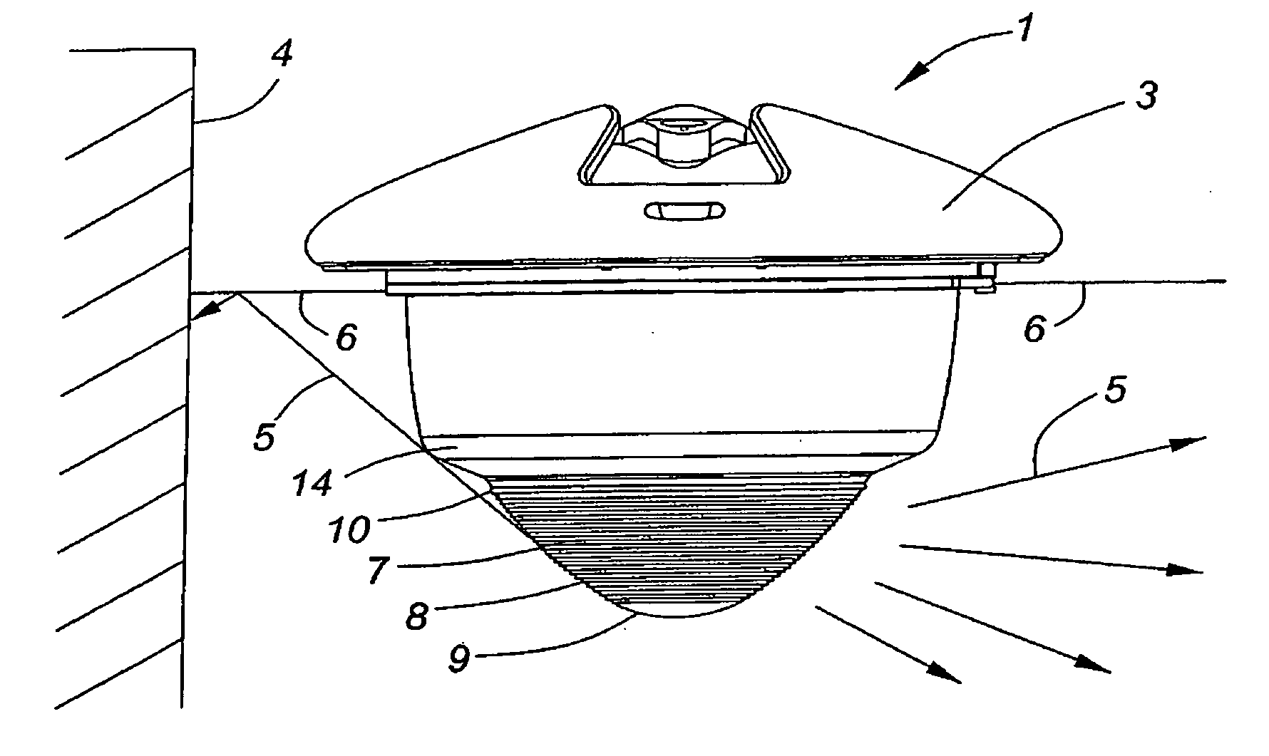
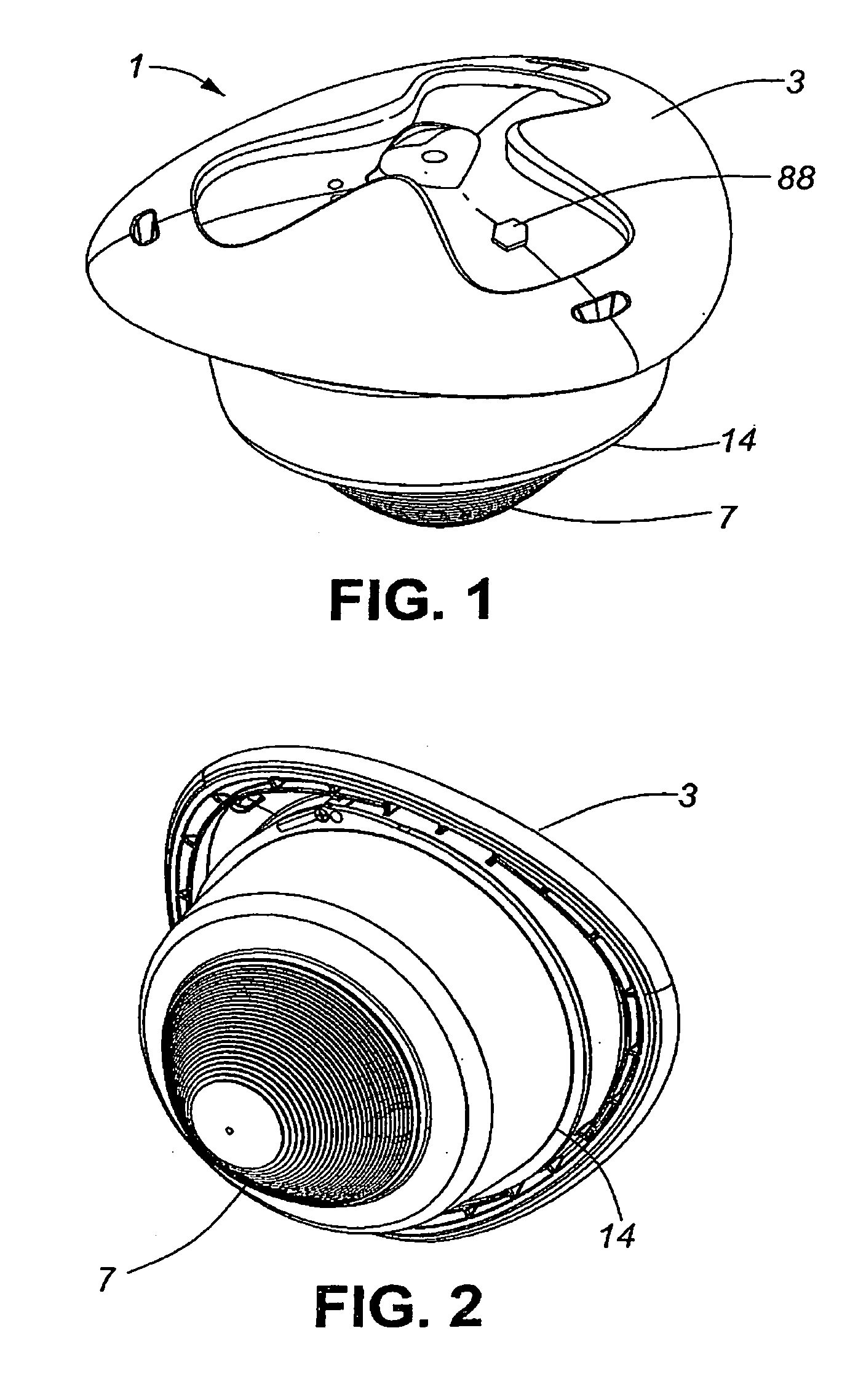
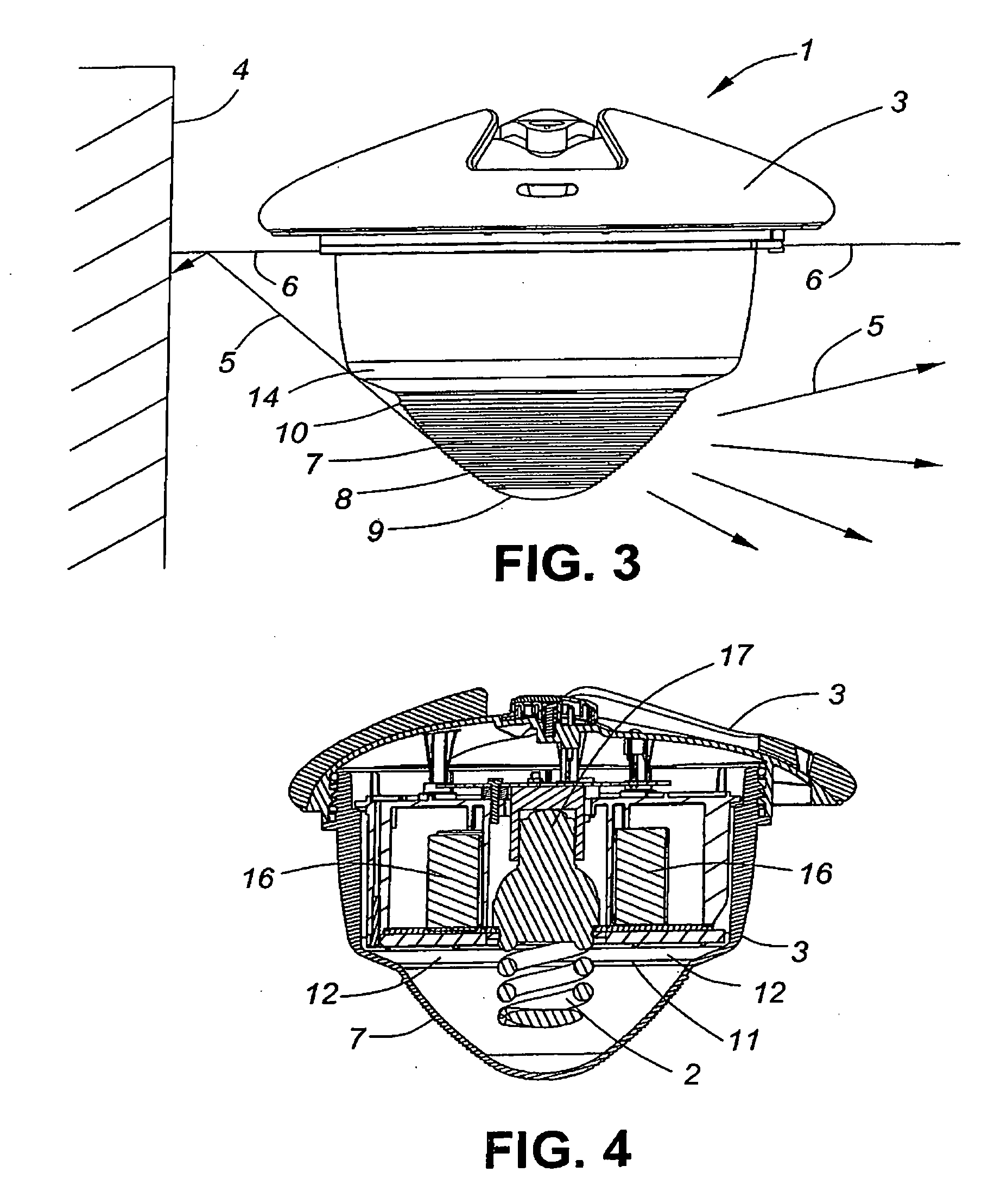
[0051] As depicted in FIGS. 1 to 6, an illumination device 1 is provided with a fluorescent tube 2 mounted in a buoyant body 3 and positioned for projecting light into a body of water when the illumination device 1 is floated on the surface of such body of water. The source of illumination, the fluorescent tube 2, extends a distance below the body. As shown in FIG. 3, light is emitted in directions which are distributed between the horizontal and vertical directions, but preferably light is directed outwardly in the horizontal direction, permitting illumination from the light source to more preferably strike the sides 4 of the pool.

[0052] More light is directed laterally and downward. The boundary between lateral and downward directions may be taken as a 45 degree downward inclination from the horizontal.

[0053] A portion of the emitted light 5, preferably more than 20%, is directed at an upward angle which takes advantage of reflection off of the underside surface 6 of the air-wat...


PUM


Abstract

A self-powered illumination device includes an illumination source protruding from its lower surface for projecting light into a body of water to provide light that is emitted preferentially outwardly to illuminate the sides of a pool. Light emitted with an upward angle of inclination strikes the underside surface of the water-air interface surrounding the device and is reflected outwardly and laterally away the from the light source after striking such underside surface. Preferably, the illumination source has a length that extends downwardly that is commensurate or greater than its width and may be in the form of a fluorescent tube. The illumination device is fully self righting when inverted on the surface of a body of water.

Description

FIELD OF THE INVENTION [0001] This invention relates to a self-powered light source which, in its preferred embodiment, is adapted for floating on the surface of a body of water. Additionally, this light source, when combined with other components, has an extended number of applications. BACKGROUND OF THE INVENTION [0002] Existing systems for illuminating pools often rely on pool-wall mounted lights. Almost invariably such lights are at least partially recessed or, at most, are flush with a wall surface upon which they are mounted. The consequence is that, even when a floodlight is employed, the illumination is virtually exclusively directed to surfaces facing the light, with very little light being directed to lateral wall surfaces. Further, being mounted on the side of the pool, illumination is developed which is not symmetrical about the central area of the pool. [0003] An advantage of a floating light source is that it may be placed more centrally within the pool than a wall-mou...

Claims


Application Information

Patent Timeline
Patent Type & Authority Applications(United States)
IPC IPC(8): F21L4/00
CPCF21S8/00F21S9/02F21V17/14F21V23/0435F21V23/0442F21W2131/401
Inventor KENNEDY, MILESTUTTON, JOHN CHARLESBALATTI, ALDOBOSCH, MARCUS WILLI KARL GERHARD
Owner ULTRA LIGHT FLOATING OBJECTS
Why Eureka
Try Eureka