
Softrouter dynamic binding protocol

a dynamic binding and softrouter technology, applied in the field of networkwork, can solve the problems of shared failure, difficult and cumbersome to achieve in a network of autonomous and complex routers, and increasing complexity of traditional router architectures

Active Publication Date: 2006-05-04
NOKIA TECHNOLOGLES OY
View PDF24 Cites 62 Cited by
  • Summary
  • Abstract
  • Description
  • Claims
  • Application Information

AI Technical Summary

Benefits of technology

[0011] Yet another embodiment is a dynamic binding protocol process including booting a control element (CE) to bring it from a down state to an up state. The CE receives solicitation messages. The CE propagates its identity though advertisement messages. It is determined whether the CE is associated with any forwarding elements (FEs) and, if so, the CE controls them.
[0012] Still another embodiment is a dynamic binding protocol process including booting a forwarding el

Problems solved by technology

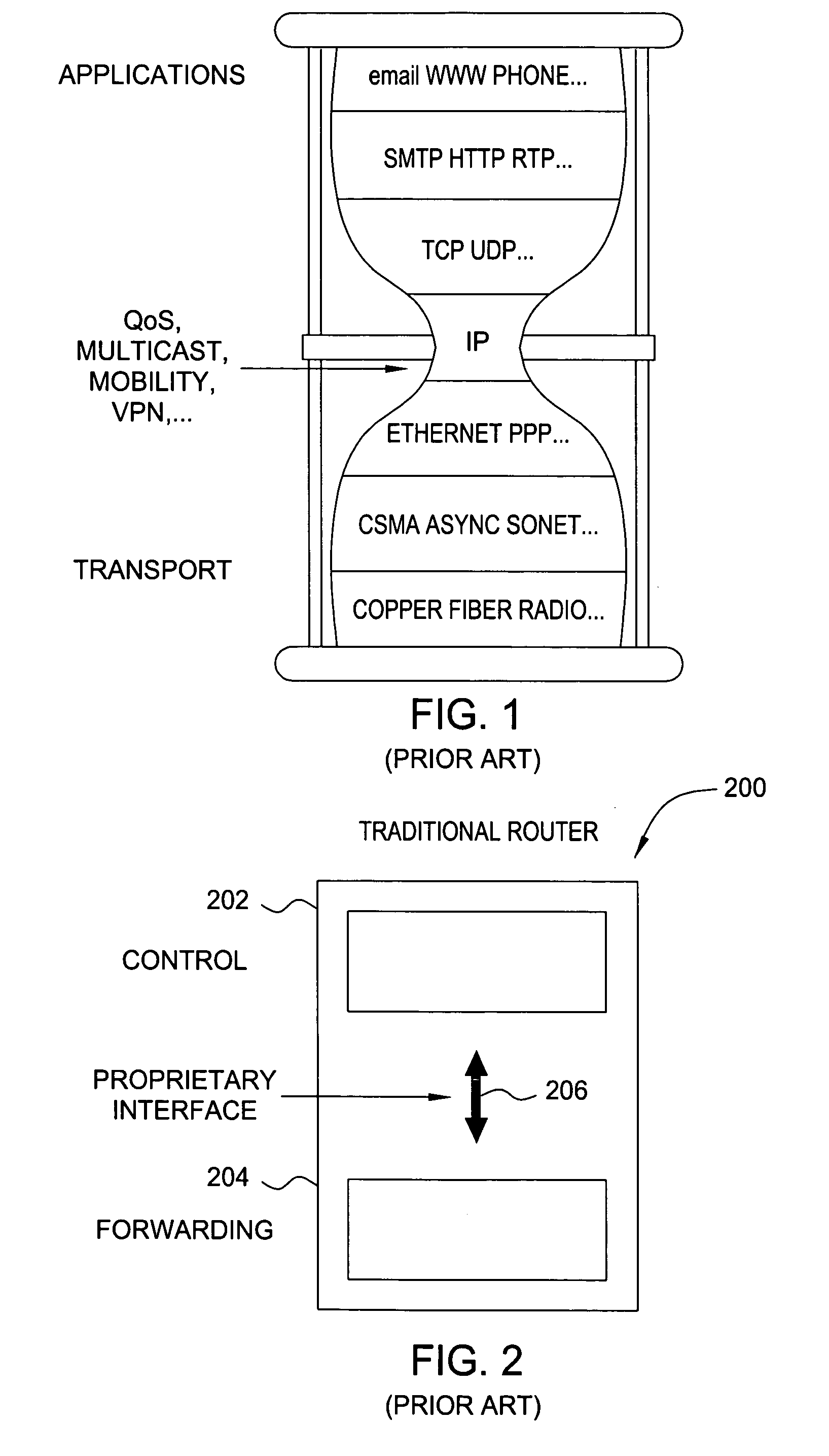
Traditional router architectures are becoming increasingly complex today as more and more features are being added to the Internet control plane.
Many operational tasks such as routing policy enforcement or traffic engineering require network-wide control that is difficult and cumbersome to achieve in a network of autonomous and complex routers.
Moreover, current routers have the route controllers tightly coupled with the forwarding engine and this static binding often results in shared failures.
Despite the end-to-end architecture design principle that aims at a simple core network, traditional router architectures have gotten increasingly complex today.
As new features are being defined by the Internet Engineering Task Force (IETF) in requests for comments (RFCs), more and more control plane complexity is being added at the routers.
In fact, the code complexity of an IP router now rivals that of a telephony switch.
The potentially unmanageable complexity is present at many points all over the network.
This has many undesirable consequences.
First, the multiple points of control significantly increase operational complexity (e.g., misconfiguration).
Second, in certain circumstances, uncoordinated actions of these autonomous routers can lead to sub-optimal performance (e.g., poor recovery time) at best and network instability in the worst case.
Finally, the introduction of new features may require upgrades to a large number of routers, which is both complex and error-prone.
The control processors provide control functions only to the co-located line cards, and vice-versa, leading to a scenario where the line cards cannot be managed when there is a failure of the co-located controller(s).

Method used


Image

  • Softrouter dynamic binding protocol
  • Softrouter dynamic binding protocol
  • Softrouter dynamic binding protocol

Examples


Embodiment Construction

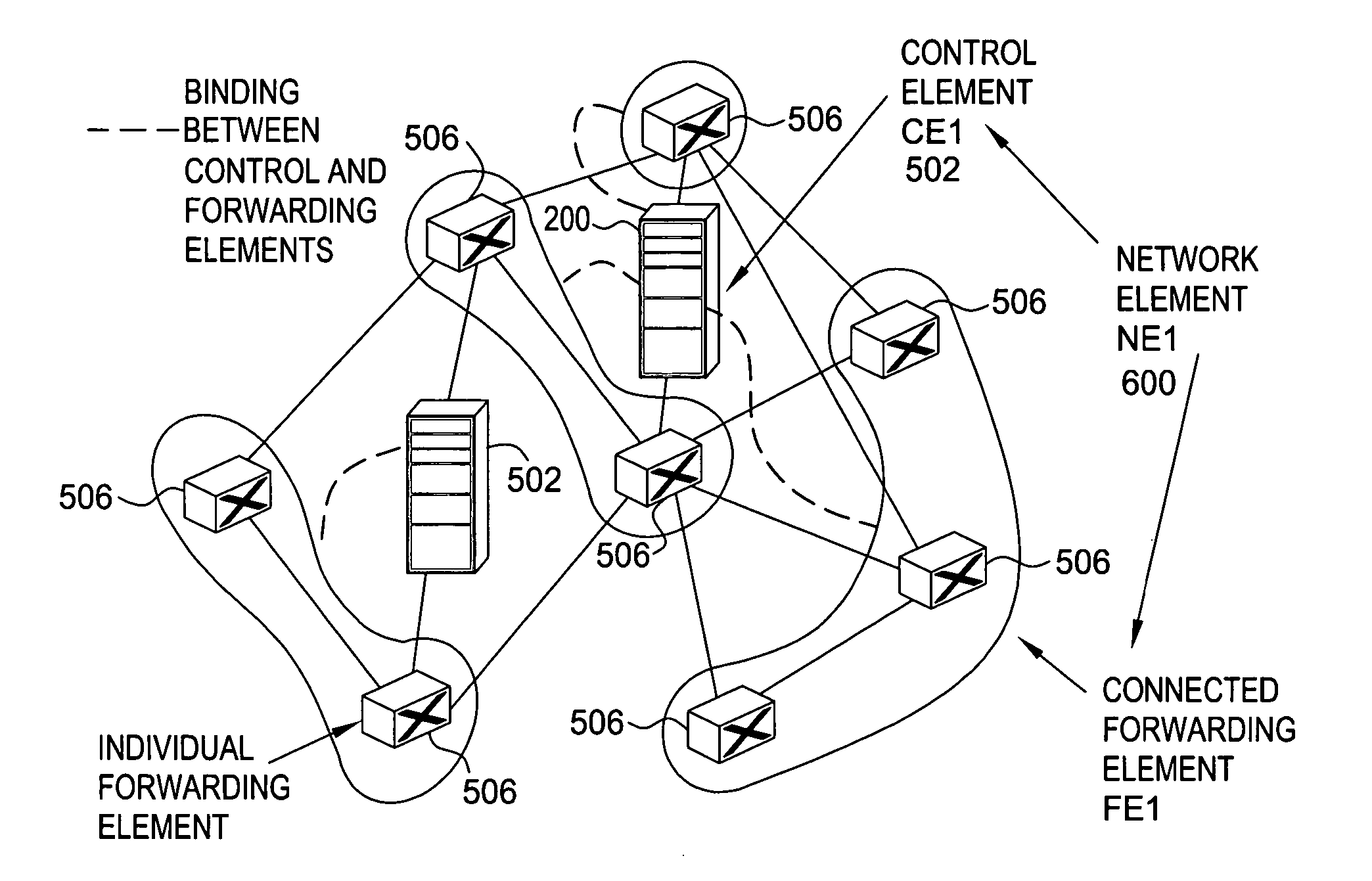
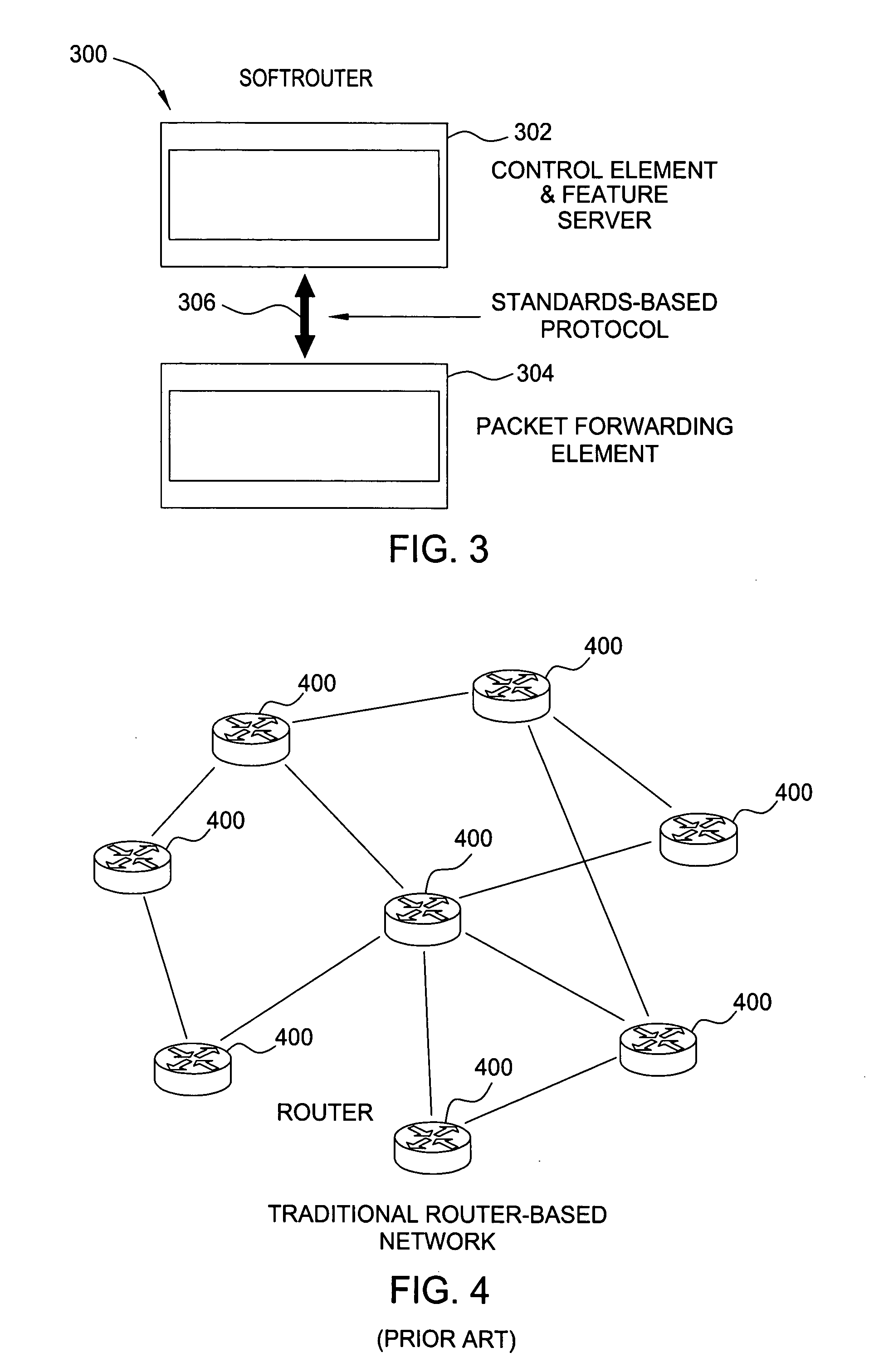
[0044] The invention will be primarily described within the general context of an embodiment of an exemplary SoftRouter architecture, however, those skilled in the art and informed by the teachings herein will realize that the disaggregation concept may be used to generate various other embodiments of network architectures and that the invention is applicable to local area networks (LANs), metropolitan area networks (MANs), wide area networks (WANs), and other networks, many open systems interconnection (OSI) layers, gateway protocols, serial line protocols, protocol stack routing and bridging protocols, many other protocols, traffic management, optical, edge / core routing, wireless, cable, data centers, auxiliary signal path (ASP), fault management, configuration management, accounting management, performance management, security management, other network management, enterprise, government, military applications, and many other different kinds of networking characteristics and appli...


PUM


Abstract

A dynamic binding protocol has three tasks that run in parallel: discovery, association, and operation. During discovery, control elements (CEs) and forwarding elements (FEs) learn about immediate neighbors and CEs in a SoftRouter network that has separate control and data planes. During association, FEs associate with CEs and are configured with basic parameters, such as IP interface addresses, hostnames, and the like. During operation, failover and packet tunneling between CEs and FEs is handled.

Description

CROSS-REFERENCES [0001] The present application claims the benefit of provisional application No. 60 / 623,885, entitled “SoftRouter: Router Disaggregation,” Attorney Docket No. Lakshman 35-2-23-62-31, filed Nov. 1, 2004. In addition, the present application is related to copending applications “SoftRouter,” Ser. No. ______ Attorney Docket No. Lakshman 35-2-23-62-31 (LCNT / 126770), “SoftRouter Protocol Disaggregation,” Ser. No. ______ Attorney Docket No. Ansari 2-2-41-3-24-34 (LCNT / 127305), “SoftRouter Protocol Failovers,” Ser. No. ______ Attorney Docket No. Ansari 3-42-4-25-35 (LCNT / 127306), “SoftRouter Separate Control Network,” Ser. No. ______ Attorney Docket No. Lakshman 43-64-36 (LCNT / 127307), “SoftRouter Feature Server,” Ser. No. ______ Attorney Docket No. Lakshman 44-65-37 (LCNT / 127308), which were filed on the same date as the present application. The provisional and related applications are incorporated herein by reference in their entireties.FIELD OF THE INVENTION [0002] The ...

Claims


Application Information

Patent Timeline
IPC IPC(8): H04L12/28H04L12/56H04L45/02H04L45/24H04L45/28
CPCH04L45/02H04L45/22H04L45/60H04L45/28H04L45/26G06F15/16H04L69/00H04L65/00
Inventor ANSARI, FURQUAN AHMEDHAVEMANN, MARTINLAKSHMAN, TIRUNELL V.NANDAGOPAL, THYAGARAJANRAMJEE, RAMACHANDRANWOO, THOMAS Y.
Owner NOKIA TECHNOLOGLES OY
Learn More