
Method and system for adjusting DC offset slice point in an RF receiver

Inactive Publication Date: 2006-05-04
AVAGO TECH INT SALES PTE LTD
View PDF12 Cites 14 Cited by
  • Summary
  • Abstract
  • Description
  • Claims
  • Application Information

AI Technical Summary

Benefits of technology

[0012] A system and/or method for adjusting a DC offset slice point in an RF receiver, substantially as shown

Problems solved by technology

The DC offset due to frequency mismatch can adversely affect the data extracted from the IF or baseband signals.

Method used


Image

  • Method and system for adjusting DC offset slice point in an RF receiver
  • Method and system for adjusting DC offset slice point in an RF receiver
  • Method and system for adjusting DC offset slice point in an RF receiver

Examples


Embodiment Construction

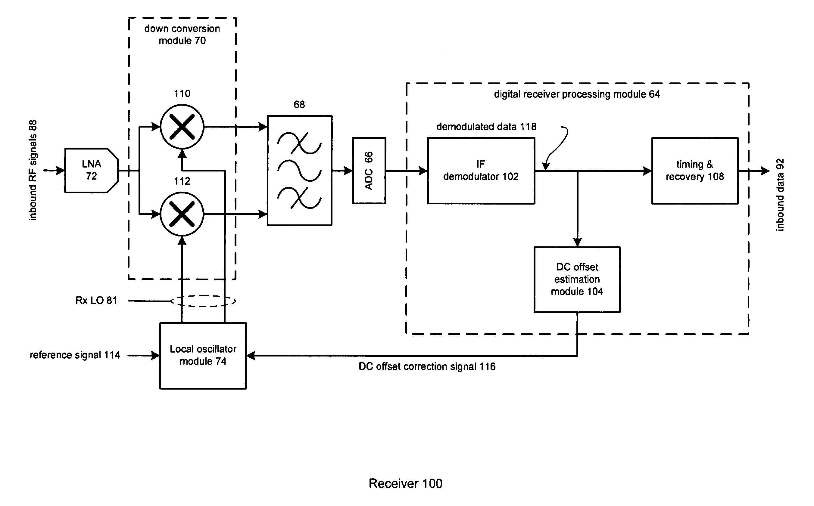
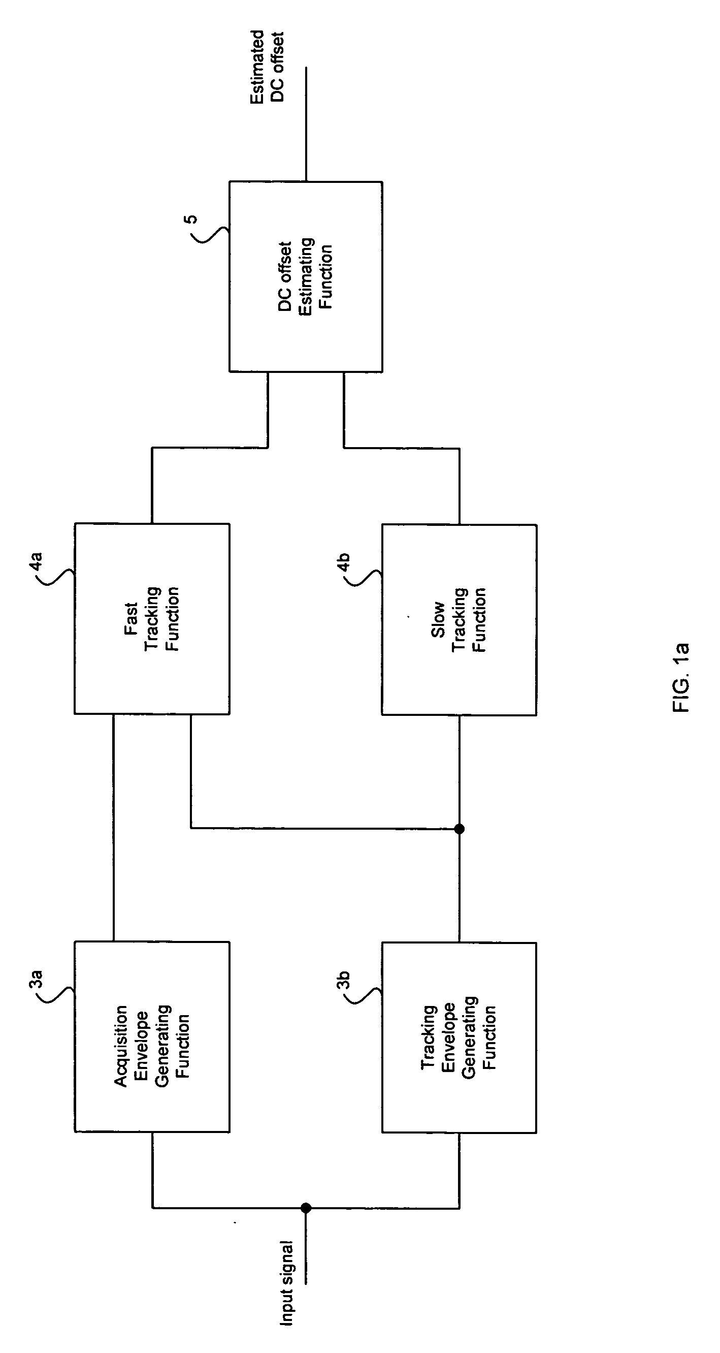
[0030] Certain embodiments of the invention provide a method and system for adjusting a DC offset slice point in an RF receiver. One aspect of the invention may provide a method for increasing the likelihood that a synchronization word or pattern may be identified in light of a DC offset. Accordingly, an embodiment of the invention may acquire an initial synchronization (SYNC) word by estimating a DC offset for the received signals. In this manner, the estimated DC offset may be utilized to determine whether the received signal is logic 1 or logic 0. This may be referred to as slicing a received signal to a 1 or a 0. A point of the DC offset used to slice the received signal may be referred to as a slicing point. Tracking circuitry may generate a fast tracking output signal that may quickly track received synchronizing signals. The tracking circuitry may also generate a slow tracking output of the received signals whose rate of change may be less than that of the fast tracking outpu...


PUM


Abstract

A method for adjusting a DC offset slice point in an RF receiver is provided and may comprise estimating DC offset using a combination of fast tracking of an input signal and slow tracking of an input signal. If both are used, the fast tracking may be executed prior to executing the slow tracking. The fast tracking may acquire synchronizing signals transmitted before a payload. Additionally, noise tolerance may be increased in the fast tracking and the slow tracking by using tracking envelopes. The fast tracking may average acquisition envelopes and tracking envelopes using a fast tracking weighting factor to a sum of the acquisition envelopes and a slow tracking weighting factor to a sum of the tracking envelopes. Additionally, the slow tracking may average the tracking envelopes.

Description

CROSS-REFERENCE TO RELATED APPLICATIONS / INCORPORATION BY REFERENCE [0001] This patent application makes reference to, claims priority to and claims benefit from U.S. Provisional Patent Application Ser. No. 60 / 624,011 filed on Nov. 1, 2004. [0002] This application makes reference to: U.S. patent application Ser. No. ______ (Attorney Docket No. 16240US02) filed Apr. 8, 2005; U.S. patent application Ser. No. ______ (Attorney Docket No. 16241US02) filed Apr. 8, 2005; U.S. patent application Ser. No. ______ (Attorney Docket No. 16242US02) filed Apr. 8, 2005; [0003] The above state applications are hereby incorporated herein by reference in their entirety.FIELD OF THE INVENTION [0004] Certain embodiments of the invention relate to processing RF signals. More specifically, certain embodiments of the invention relate to a method and system for adjusting a DC offset slice point in an RF receiver. [0005] This invention relates generally to wireless communication systems and more particular...

Claims


Application Information

Patent Timeline
IPC IPC(8): H04L27/06H04L27/14
CPCH04L25/062H04L27/142
Inventor KIM, HEA JOUNGIBRAHIM, BRIMAJENSEN, HENRIK THOLSTRUP
Owner AVAGO TECH INT SALES PTE LTD
Learn More