Fan with central intake

a technology of fan and central intake, which is applied in the direction of machines/engines, stators, liquid fuel engines, etc., can solve the problems of stagnation zone, slow cooling speed, and inability to achieve proper heat dissipation, so as to reduce the stagnation zone produced by the fan, remove the heat from the cooling of an article, and enhance heat dissipation

Inactive Publication Date: 2006-05-04
ASIA VITAL COMPONENTS SHENZHEN CO LTD
View PDF7 Cites 13 Cited by
  • Summary
  • Abstract
  • Description
  • Claims
  • Application Information

AI Technical Summary

Benefits of technology

[0012] A primary object of the present invention is to provide a fan with central intake in which a flow route is disposed at the center of the fan to reduce a stagnation zone produced by the fan and so as to remove heat from an article being cooled and enhance heat dissipation effectively.
[0013] Another object of the present invention is to provide a fan with central intake in which a flow route is disposed at the center of the fan to remove heat from a joining part and a driving device so as to enhance operation efficiency of the fan.

Problems solved by technology

Otherwise, the central processor will be shutdown resulting from overheat if there is no excellent heat dissipation device.
But, the main unit of a computer provides a limited space for the fan being located so that how to promote function of heat dissipation with a fan in proper size becomes relatively significant.
The problem created by the conventional fan is that the fluid does not flow toward the rear side of the hub seat 111 to result in a stagnation zone 15 is created at the rear side of the hub seat 111 while the fluid flows outward and disperses toward periphery of the fan frame.
As a result, heat at the center of the radiator 16 is incapable of being dissipated and the heat dissipation capability becomes lowered.
Obviously, the conventional fan does not provide a way to discharge the heat sources and it is the reason of the conventional fan provides unfavorable effect of heat dissipation.

Method used


Image

  • Fan with central intake
  • Fan with central intake
  • Fan with central intake

Examples


first embodiment

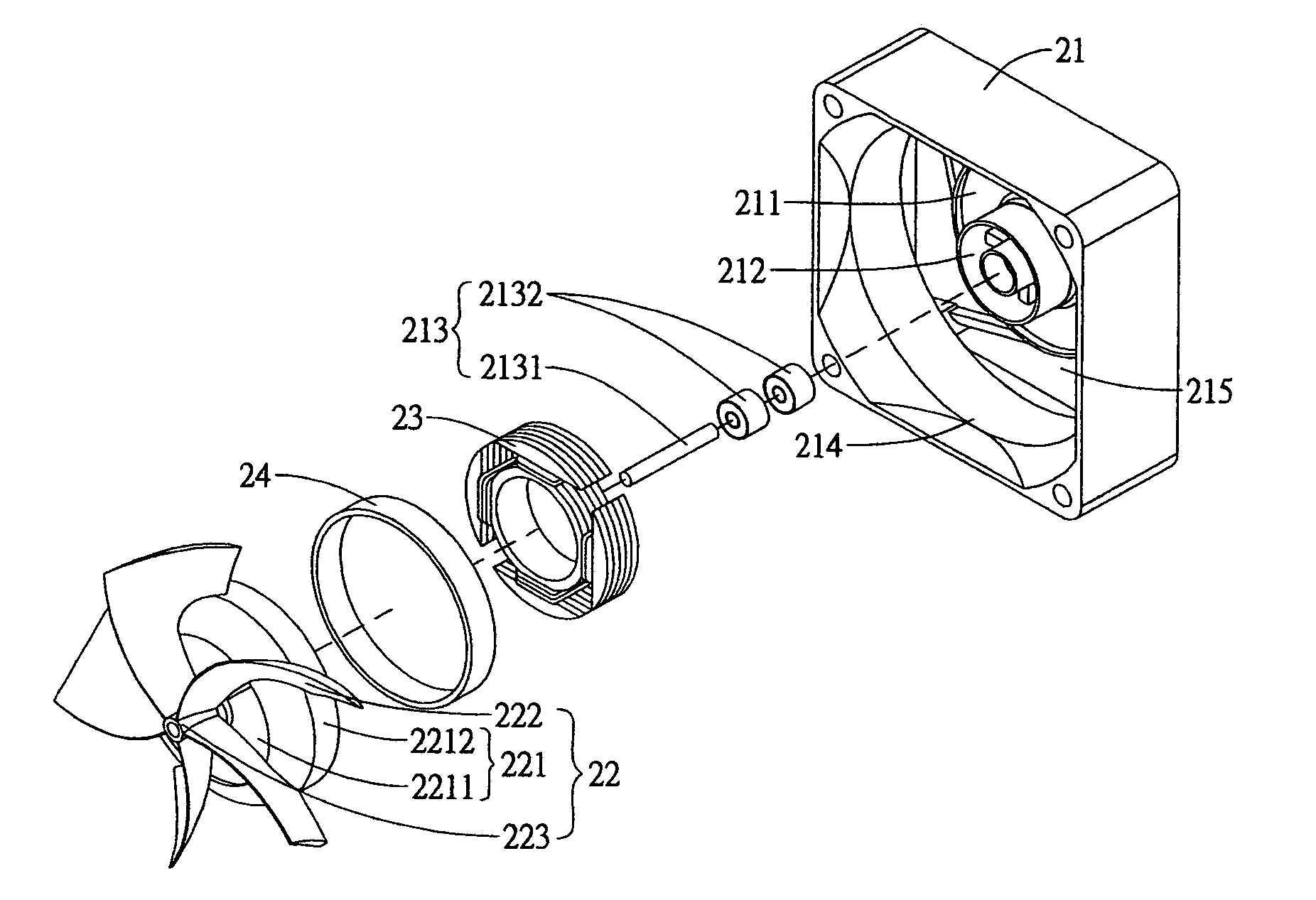
[0048] Referring to FIGS. 6 and 7, a fan with central intake according to the present invention comprises a fan frame 21 and a fan wheel 22. The fan frame 21 provides an inlet 214 and an outlet 215. A hub seat 211 is located at the outlet 215 with a central passage 212 being disposed in the hub seat 211 for fluid moving through and a joining part 213 in the passage 212. The joining part 213 is composed of a spindle 2131 and a plurality of bearings 2132. A motor stator 23 of a driving device fits with the hub seat 211. The fan wheel 22 has a hub 221 with a central through holes 2211 and a plurality of blades 222 extending radially from the outer annular surface of the hub 221. The blades 222 further extend inward to the center of an end face on the hub 221 to connect with a receiving part 223 with a twist angle turning right side. The motor rotor 24 of the driving device is received in the hub 221.

[0049] While the fan of the present invention is in assembling, the hub 221 of the fan ...

third embodiment

[0059] Referring to FIGS. 30 and 31, the passage 412 of the hub seat 411 in the third embodiment can be diverged downward from the top or converged downward from the top to control outgoing fluid and extend flowing range or control the fluid flowing toward rear side of the joining part 413 so as to allow the fluid at the rear side of the joining part 413 keeping moving and prevent from creating the stagnation zone.

[0060] Referring to FIGS. 32 and 33, the blades 422 of the fan wheel 42 in the third embodiment can be provided with a twist angle turning leftward. Under this circumstance, the fluid enters the hub seat 411 from a lateral side thereof and blows toward the radiator 46 at another side thereof so that the same effect and function can be reached as well.


PUM


Abstract

A fan with central intake comprises a fan frame, a fan wheel and a driving device. The fan frame provides a hub seat with a passage for fluid flowing through and a joining part in the passage. The fan wheel is received in the fan frame and provides a hub with a through hole being associated with the passage to constitute a central flow route and blades radially extending from an outer annular surface of the hub and extending inward to an end face of the hub to connecting with a receiving part, which is joined to the joining part The driving device is mounted to the fan frame and the fan wheel respectively to rotate the fan wheel. When the fan wheel is rotated with the driving device, the fluid moves along the central flow route to dissipate heat in the center of an article being cooled, the driving device and the joining part so as to enhance heat dissipation efficiency and running efficiency.

Description

BACKGROUND OF THE INVENTION [0001] 1. Field of the Invention [0002] The present invention is related to a fan with central intake and particularly to a fan frame with a fan wheel for dissipating heat in an electronic product. [0003] 2. Brief Description of the Related Art [0004] Due to development of electronic technology, the central processor is operated with high time pulse to satisfy requirement of high executing speed. However, the central processor with high speed of data treatment accompanies with much more heat generation too. [0005] In order to dissipate the heat, it is necessary to provide a heat dissipation device. Otherwise, the central processor will be shutdown resulting from overheat if there is no excellent heat dissipation device. [0006] Currently, the most popularly used heat dissipation device is the cooling fan because of its low cost. This is why the manufacturers are interested in developing and researching the fan. [0007] But, the main unit of a computer provi...

Claims


Application Information

Patent Timeline
Patent Type & Authority Applications(United States)
IPC IPC(8): F04D29/58
CPCF04D25/0613F04D29/582
Inventor LIU, WEN-HAOCHOU, CHU-HSIEN
Owner ASIA VITAL COMPONENTS SHENZHEN CO LTD
Why Eureka
Try Eureka