Turbine type stirrer used for molten iron mechanical stirring desulfuration

A mechanical stirring and turbine-type technology, which is applied in the field of turbine-type agitators for mechanical stirring and desulfurization of molten iron, can solve the problems of difficulty in reducing the consumption of stirring power, increasing the forward tilt angle, strengthening the agitator, etc., and achieving enhanced axial entrainment circulation volume, reducing stagnant area, increasing area and stirring the effect of radial thrust

Inactive Publication Date: 2010-10-13
武钢集团有限公司
View PDF10 Cites 10 Cited by
  • Summary
  • Abstract
  • Description
  • Claims
  • Application Information

AI Technical Summary

Problems solved by technology

However, in the above-mentioned three-bladed agitator patent, the agitating blades are evenly arranged along the circumference of the rotating shaft, and the thickness symmetry plane of the metal core of the agitating blades is in the same plane as the center line of the rotating shaft. Under the condition that three stirring blades are evenly arranged in the circumferential direction of the stirring shaft with a limited diameter, it will be difficult to further increase the angle between the stirring blades and the inclination angle of the stirring blade against the iron surface, and it is difficult to reduce the stirring power consumption. Restricts the improvement effect of enhancing the entrainment cycle mixing and shear dispersion of the agitator, delaying the speed of sticky residue and reducing the consumption of stirring power

Method used


Image

  • Turbine type stirrer used for molten iron mechanical stirring desulfuration
  • Turbine type stirrer used for molten iron mechanical stirring desulfuration
  • Turbine type stirrer used for molten iron mechanical stirring desulfuration

Examples


Embodiment Construction

[0022] Below in conjunction with accompanying drawing and specific embodiment, the turbine agitator of the present invention is described in further detail with mechanical agitation desulfurization of molten iron:

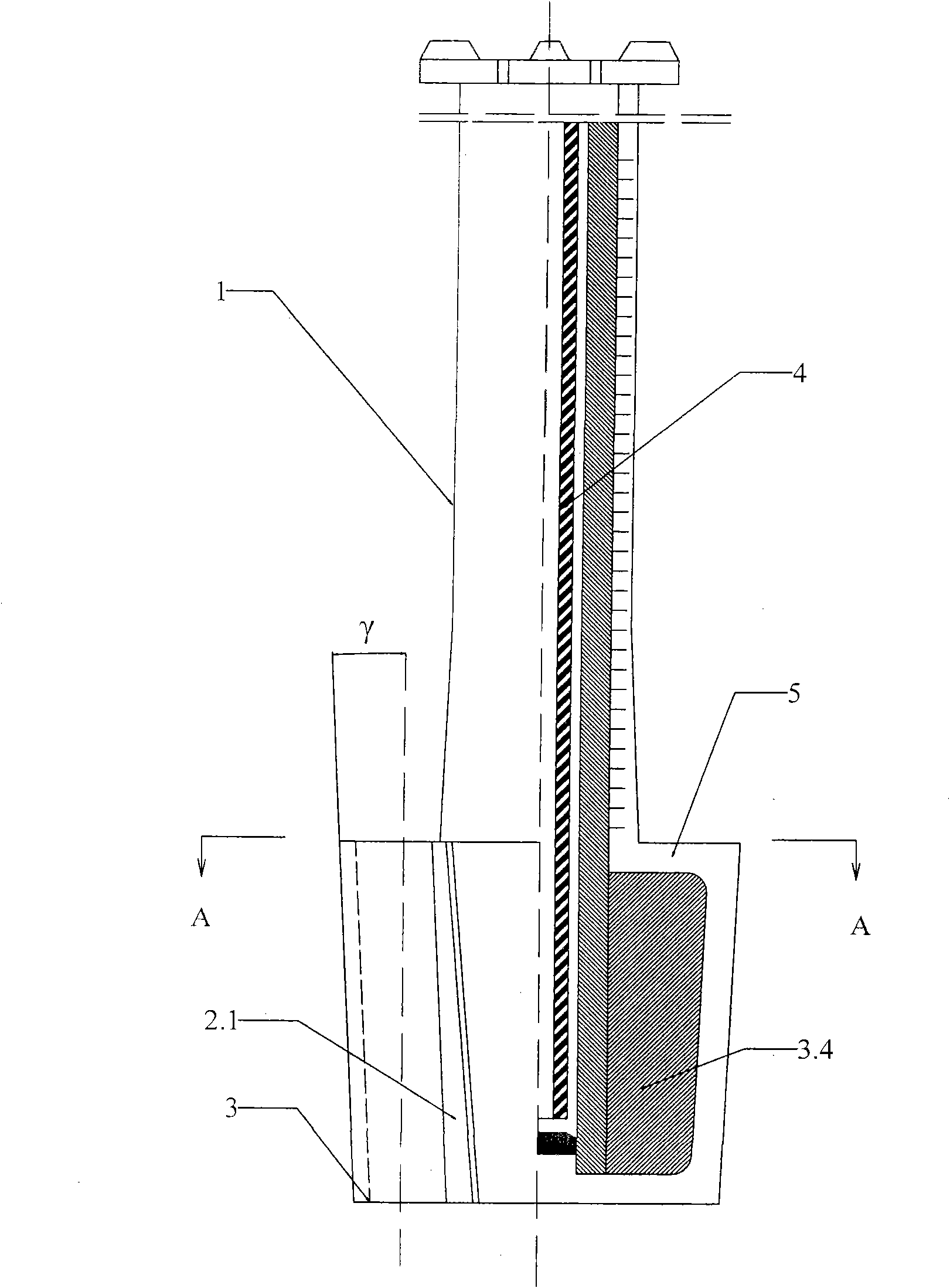
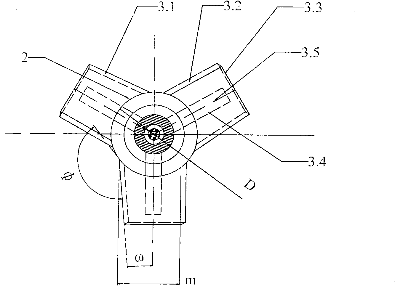
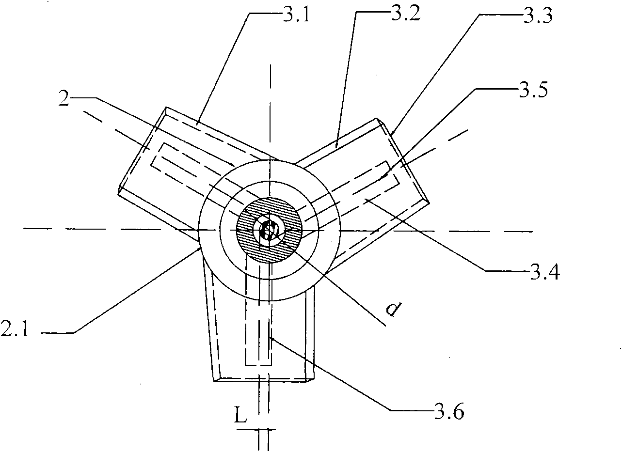
[0023] like Figure 1 to Figure 3 As shown, the turbine agitator for mechanical stirring desulfurization of molten iron of the present invention includes a rotating shaft 1, an air-cooled tube 4 placed in the rotating shaft 1, a hub 2 and three stirring blades 3 uniformly arranged around the circumference of the hub 2. The hub 2 is a frustum-shaped structure whose diameter gradually decreases from top to bottom in the axial direction, and is made of refractory material, and is cast together with the stirring blade 3 . The stirring blade 3 includes a stirring blade metal core 3.4 and a refractory working lining 5 . The iron-facing water surface 3.1, the back-iron water surface 3.2 and the side surfaces 3.3 of the stirring blade 3 are slopes inclined from bottom to to...


PUM


Abstract

The invention discloses a turbine type stirrer used for molten iron mechanical stirring desulfuration, comprising a rotating shaft, a wheel hub and three stirring vanes, wherein, each stirring vane comprises a stirring vane metal core and is evenly distributed at the periphery of the wheel hub; the surface facing melt iron, the surface deviating melt iron and the side face of the stirring vane are all inclined planes inclining forwards from bottom to top, and the angles of inclination alpha, beta and gamma respectively satisfy the following conditions: alpha is more than or equal to 1 degree and less than or equal to 10 degrees, beta is more than or equal to alpha and less than or equal to 15 degrees, and gamma is more than or equal to 0 degree and less than or equal to 3 degrees; the stirring vane metal core is in eccentric arrangement; the flat surface on which the thickness symmetry plane of the stirring vane metal core is located is a first vertical plane; the flat surface parallel to the first vertical plane and passing the centre line of the rotating shaft is a second vertical plane; the first vertical plane is overlapped with the second vertical plane horizontally moving a distance of L towards the direction of the surface facing melt iron, wherein, L satisfies the condition that L is more than 0 and less than or equal to (d-a)/2; d is the diameter of the metal core of the rotating shaft; and a is the thickness of the stirring vane metal core; by applying the invention, the stirring power consumption of the invention is low, the sticky dregs between the stirring vanes are less; and the dynamical condition of stirring desulfuration is good.

Description

technical field [0001] The invention relates to a stirring desulfurization device outside a molten iron furnace before converter steelmaking, in particular to a turbine type agitator for mechanical stirring desulfurization of molten iron. Background technique [0002] The KR (Kambara Reactor) stirring desulfurization method is a desulfurization technology outside the molten iron furnace that Nippon Steel began to study in 1963 and applied to industrial production in 1965. In this desulfurization method, a stirrer with a cross-shaped blade structure lined with refractory material is immersed in the molten iron tank to rotate and stir the molten iron, so that the molten iron generates a vortex, and the weighed desulfurizer is added to the surface of the molten iron by the feeder, and is The vortex is involved in the molten iron to mix and react with the high-temperature molten iron to achieve the purpose of desulfurization. The desulfurization method has the characteristics o...

Claims


Application Information

Patent Timeline
Patent Type & Authority Applications(China)
IPC IPC(8): C21C7/064
Inventor 欧阳德刚罗安智
Owner 武钢集团有限公司
Why Eureka
Try Eureka