Airfoil with three-pass serpentine cooling channel and microcircuit

a cooling channel and airfoil technology, applied in the direction of machines/engines, mechanical equipment, liquid fuel engines, etc., can solve the problems of less cooling efficiency, less cooling surface area of the wall adjacent the smaller side of the trapezoid, and relatively high mechanical and thermal stress

Active Publication Date: 2006-05-04
RTX CORP
View PDF3 Cites 48 Cited by
  • Summary
  • Abstract
  • Description
  • Claims
  • Application Information

AI Technical Summary

Benefits of technology

[0010] In a disclosed embodiment of this invention, an airfoil has a microcircuit cooling circuit embedded in an area between the smaller side of one of the paths of a serpentine channel and the adjacent wall. This microcircuit is provided with cooling air from one of the other paths in the serpentine channel. Further, in the disclosed embodiments, the microcircuit exhausts air through a series of small openings to provide film cooling to the surface of the airfoil at the adjacent wall.

Problems solved by technology

With such trapezoidal-shaped paths for a serpentine flow, the wall adjacent the smaller side of the trapezoid has less cooling surface area and less cooling efficiency.
Further, the serial flow paths are typically at an area of high curvature that is subject to relatively high mechanical and thermal stresses.

Method used


Image

  • Airfoil with three-pass serpentine cooling channel and microcircuit
  • Airfoil with three-pass serpentine cooling channel and microcircuit
  • Airfoil with three-pass serpentine cooling channel and microcircuit

Examples


embodiment 150

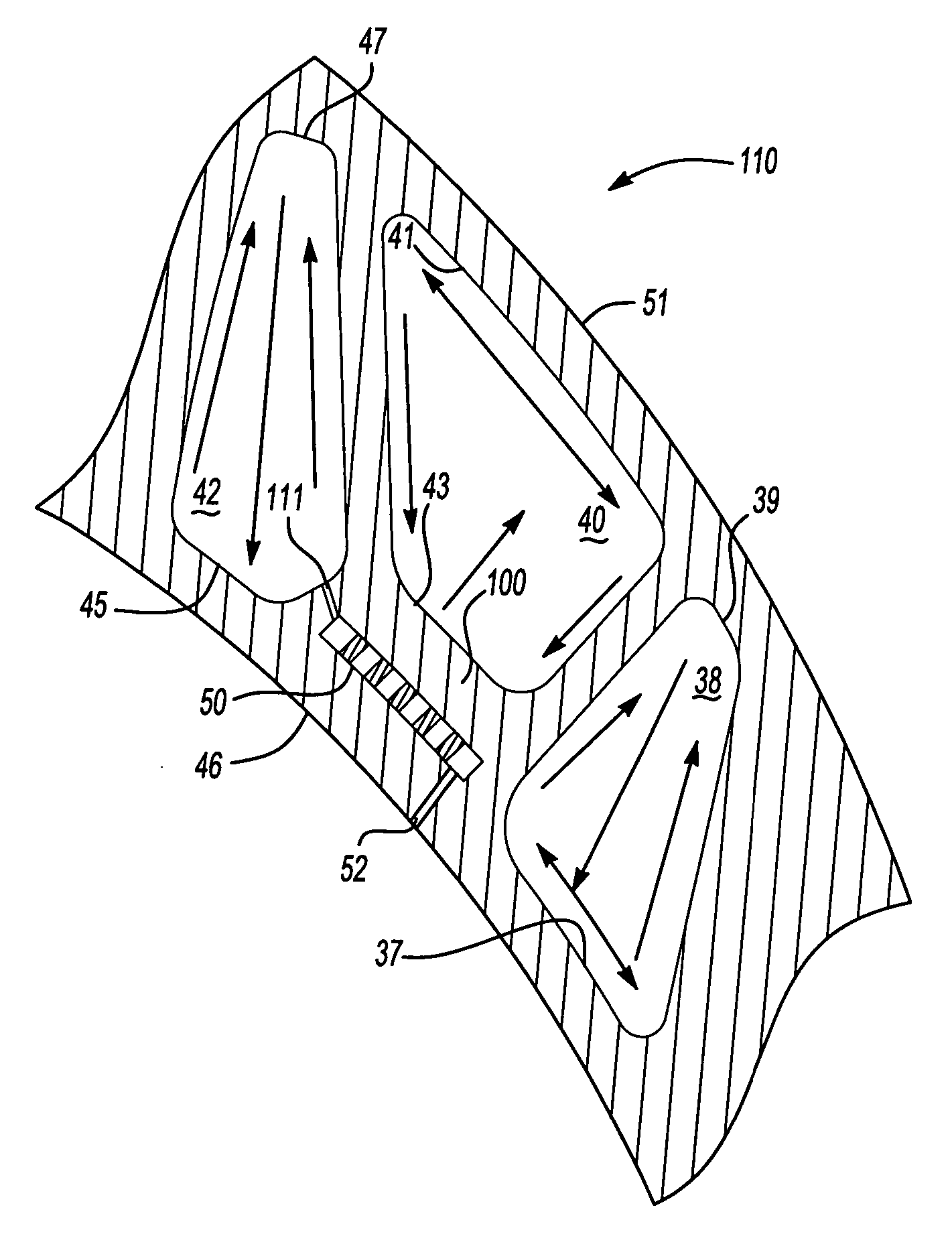
[0035]FIG. 7 shows another microcircuit embodiment 150 wherein the microcircuit is positioned in the area 101 between the smaller side 39 of the path 38 and the suction wall 51. Here again, an inlet passage 154 communicates cooling air from another of the serpentine channel paths 40. Pedestals 152 are placed within the microcircuit 150, and an exhaust port 160 communicates film cooling air to the suction wall 51. The embodiment of FIG. 7 would preferably include a plurality of spaced microcircuits 150 similar to that shown in FIG. 6.

[0036] The detail of the microcircuit can have many distinct shapes, positions, spacings, etc., and varying numbers of entry / exhaust passages per microcircuit, and relative shapes and sizes of the pedestals. Several available options are described below, however, these are merely exemplary. That is, the microcircuits 50 of FIG. 5 and the microcircuits 150 of FIG. 7 can have the configuration of FIG. 8 or 9, or some other configuration. For purposes of th...

first embodiment

[0057] Advantageously, the positioning of the pedestals 396, as described above, permits very good metering control of the cooling air as it exits through the respective exit aperture 52. More specifically, as the cooling air passes through rows 382 and 384, the air impinges onto the pedestals 396 and is directed around the pedestals to exit through the corresponding exit aperture 52. Also, in this way and as shown by the streamlines, 0, 1, 1′, the main streamline 0 provides for uniform flow distribution out through the exit aperture 52. That is to say, the streamlines 1 do not cross with the streamlines 1′ and visa versa. The main streamline, 0, like that of the first embodiment shown in FIG. 8, is generally aligned with the center of the corresponding exit aperture 52. However, in the alternative embodiment, the pedestals 396 are aligned with the exit aperture 52 such that the majority of the length, L3, of the pedestals 396 are exposed to the exit aperture 52. As such, the stream...


PUM


Abstract

An airfoil, and in a disclosed embodiment a rotor blade, has a serpentine cooling path. To best account for the Coriolis effect, the paths of the serpentine cooling channel have trapezoidal cross-sections. An area of the rotor blade between a smaller side of the trapezoidal-shaped paths, and a facing wall of the rotor blade has high thermal and mechanical stresses, and is a challenge to adequately cool. A microcircuit, which is a very thin cooling circuit having crossing pedestals, is embedded into the blade in this area. The microcircuit provides additional cooling, and addresses the challenges with regard to cooling these areas.

Description

BACKGROUND OF THE INVENTION [0001] This invention relates to a cooling scheme for use in an airfoil, such as a turbine blade, or vane, wherein a serpentine cooling channel is supplemented by an additional cooling microcircuit at an area of high stress. [0002] Turbine blades are utilized in gas turbine engines. As known, a turbine blade typically includes a platform, with an airfoil shape extending above the platform. The airfoil is curved, extending from a leading edge to a trailing edge, and between a pressure wall and a suction wall. [0003] Cooling circuits are formed within the airfoil body to circulate cooling fluid, typically air. One type of cooling circuit is a serpentine channel. In a serpentine channel, air flows serially through a plurality of paths, and in opposed directions. Thus, air may initially flow in a first path from a platform of a turbine blade outwardly through the airfoil and reach a position adjacent an end of the airfoil. The flow is then returned in a secon...

Claims


Application Information

Patent Timeline
Patent Type & Authority Applications(United States)
IPC IPC(8): F01D5/18
CPCF01D5/187F01D5/189F05D2250/185Y02T50/676F05D2250/23F05D2260/202F05D2260/22141F05D2250/13Y02T50/60F01D5/18
Inventor CUNHA, FRANK J.TELLER, BRETCHON, YOUNGMONGILLO, DOMINICPIETRASZKIEWICZ, EDWARD F.
Owner RTX CORP
Why Eureka
Try Eureka