Centrifuge bowl for separating particles

a centrifuge and particle technology, applied in centrifuges, suction devices, material testing goods, etc., can solve the problems of serious medial complications, short half-life of platelets, and limited number of donors, so as to reduce the flow velocity of the prp fraction, slow sedimentation velocity, and fast sedimentation velocity

Inactive Publication Date: 2002-10-03
HAEMONETICS
View PDF0 Cites 41 Cited by
  • Summary
  • Abstract
  • Description
  • Claims
  • Application Information

AI Technical Summary

Benefits of technology

0049] When platelets and white blood cells contained in the PRP fraction enter the cavity 20, they first move along the Ekman layers E1, E2 and then the Stewartson layers S1, S2, and are separated by centrifugal elutriation. In particular, when the PRP fraction flows through the Ekman layers E1 and E2, because platelets have a slower sedimentation velocity than white blood cells, the platelets are dragged by fluid flow more rapidly than the white blood cells toward the outlet slot 22. Part of the white blood cells, if not most, are retained in the Ekman layers because of their faster sedimentation velocity. In the Stewartson layers S1 and S2, while platelets (represented by "x") are subjected to an axial dragging force D created by the flow of viscous plasma and allowed to proceed to the outlet slot 22, larger white blood cells (represented by "o") are subjected to a centrifugal force C created by the rotation of the centrifuge 10 and taken into the internal regio

Problems solved by technology

As is well known, platelets have a short half-life of 4-6 days and the number of donors is usually limited.
Further, it is known that contamination of concentrated platelet products with white blood cells can lead to serious medial complications, such as GVH reactions.
However, the centrifugal elutriation with this type of chamber suffers from a number of inherent disadvantages.
This reduces the effectiveness of the centrifugal elutriation considerably.
Another problem with the prior art centrifugal elutriation is cell mixing by density inversion.
This condition is unstable and may lead to turnover and turbulent mixing when the centrifugal

Method used


Image

  • Centrifuge bowl for separating particles
  • Centrifuge bowl for separating particles
  • Centrifuge bowl for separating particles

Examples


example 1

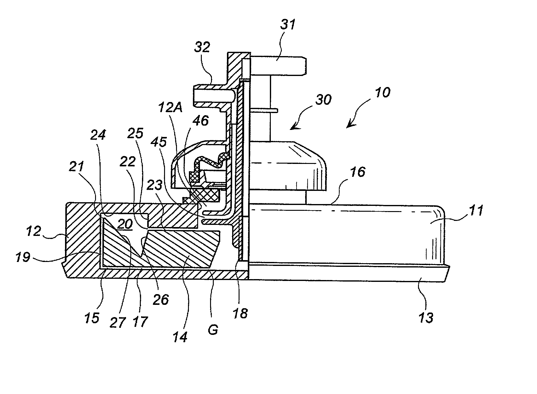
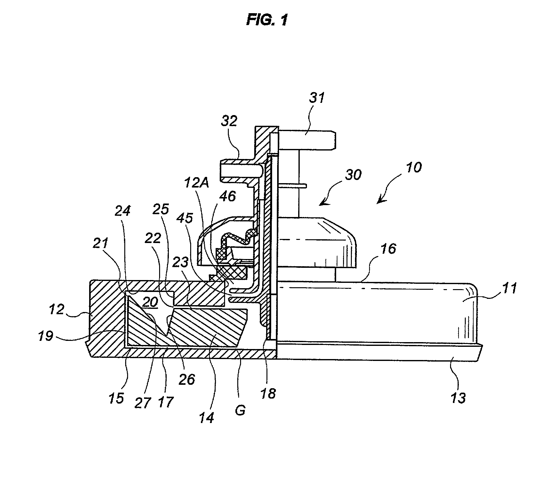
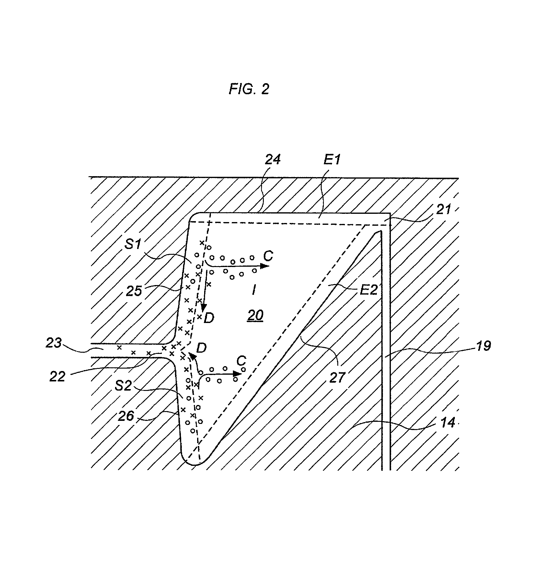
[0064] A single cavity centrifuge bowl having the construction shown in FIG. 1 was prepared. The outer diameter of the inner cavity 20 was about 50 mm and the inner diameter was about 33 mm. The maximum height of the cavity 20 was about 20 mm and the axial offset between the inlet and outlet peripheral slots 21 and 22 was about 10 mm. The volume of the cavity 20 was approximately 35 ml. The upper annular wall 24 was generally horizontal but the inclined wall 27 contained about 37 degrees with the axis of rotation.

[0065] The centrifuge bowl was mounted on a centrifuge machine for rotation, with the rotary seal assembly 30 fixedly supported. The bowl was initially filled with saline solution pumped at a predetermined flow rate and the bowl was started to rotate at a predetermined speed. After two minutes of feeding the saline, valves were operated to change the flow from saline to a fractionated whole blood containing platelets and white blood cells suspended in plasma. After switchin...


PUM


Abstract

A novel centrifuge bowl for processing particles suspended in a fluid is disclosed. The centrifuge bowl includes an annular cavity concentrically located about the rotation axis for suitably separating particles of similar densities but of different diameters. The cavity is preferably configured to have an annular cross sectional area, which is parallel to the rotation axis, that increases from a centrifugal side of the cavity toward a centripetal side of the cavity. This configuration allows to generate an almost rigidly rotating field upon rotation of the centrifuge bowl, which field helps to uniformly disperse Coriolis force throughout the circumference of the cavity to avoid turbulent mixing of the particles. In an alternative embodiment, the cavity is surrounded by an outer cavity for separating particles according to density before processing them through the inner cavity. This construction is particularly suitable for processing whole blood to harvest platelet-rich-plasma with reduced level of white blood cell contamination.

Description

[0001] The present invention relates to the field of separating particles, in particular to a centrifuge bowl for separating particles of differing size and / or density suspended in a fluid. More specifically, when applied to the medical field, the present invention relates to an improved centrifuge bowl which enables to produce a blood product with a substantially lower level of contamination with white blood cells.[0002] In many fields of technology, it is desired to separate particles suspended in a fluid. For example, in the medical field, it is desired to fractionate whole human blood for transfusion purposes. Specifically, whole human blood includes blood cells such as red blood cells, white blood cells and platelets and these cells are suspended in plasma, an aqueous solution of proteins and other chemicals. Today, blood transfusions are widely given by transfusing only those blood components required by a particular patient instead of using a transfusion of whole blood. Trans...

Claims


Application Information

Patent Timeline
IPC IPC(8): A61M1/02G01N33/48B04B1/08B04B1/12B04B5/04B04B7/08
CPCA61M1/3693B04B5/0442B04B2005/0471B04B2005/0464B04B7/08A61M1/3696
Inventor SAKOTA, KOICHIRO
Owner HAEMONETICS
Why Eureka
Try Eureka