
Secondary battery and a secondary battery module using the same

a secondary battery and secondary battery technology, applied in the field of secondary batteries, can solve the problems of increasing connection resistance, decreasing electric conductivity, and reducing current collecting efficiency, so as to improve the terminal connection structure of unit batteries, improve the efficiency of electric conductivity and current collecting efficiency, and maximize the contact area

Inactive Publication Date: 2006-05-04
SAMSUNG SDI CO LTD
View PDF8 Cites 51 Cited by
  • Summary
  • Abstract
  • Description
  • Claims
  • Application Information

AI Technical Summary

Benefits of technology

[0010] In order to solve one or more of the aforementioned problems, embodiments of the present invention provide a secondary battery with better electric conductivity and current collecting efficiency by improving the terminal connection structure of unit batteries to maximize the contact areas with a terminal, and a secondary battery module using the same.
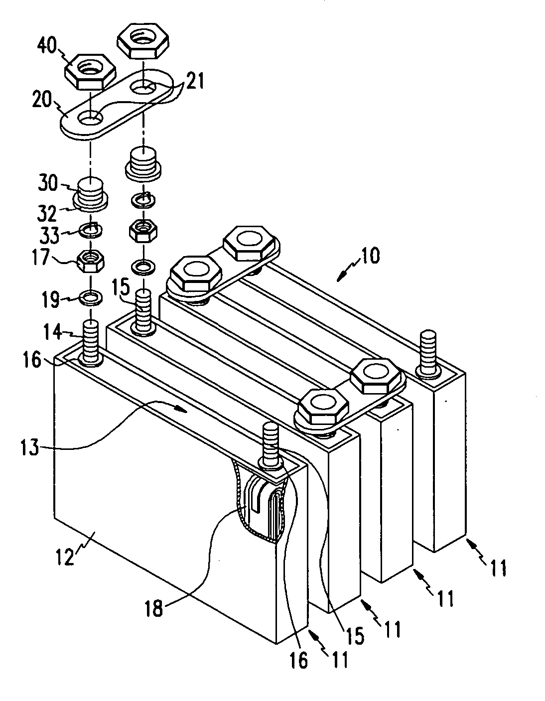
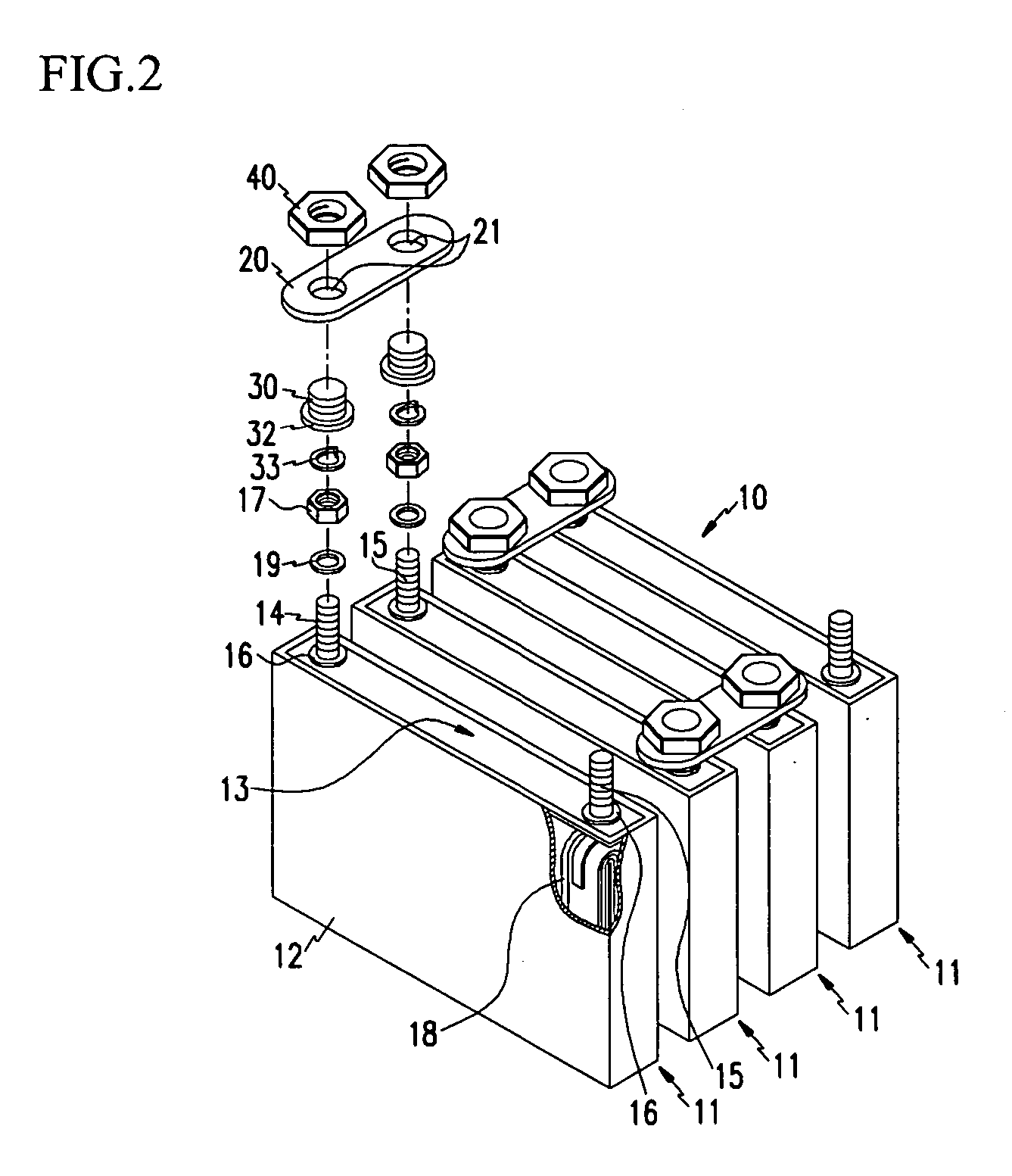
[0012] Therefore, the connecting member, which electrically connects the first terminal with the connector, increases the contact area between the first terminal and the connector, eventually increasing electric conductivity.
[0019] Accordingly, the connecting member, which electrically connects a terminal and a connector, contacts a substantial surface of the terminal and increases the connector's its contact area, increasing electric conductivity.

Problems solved by technology

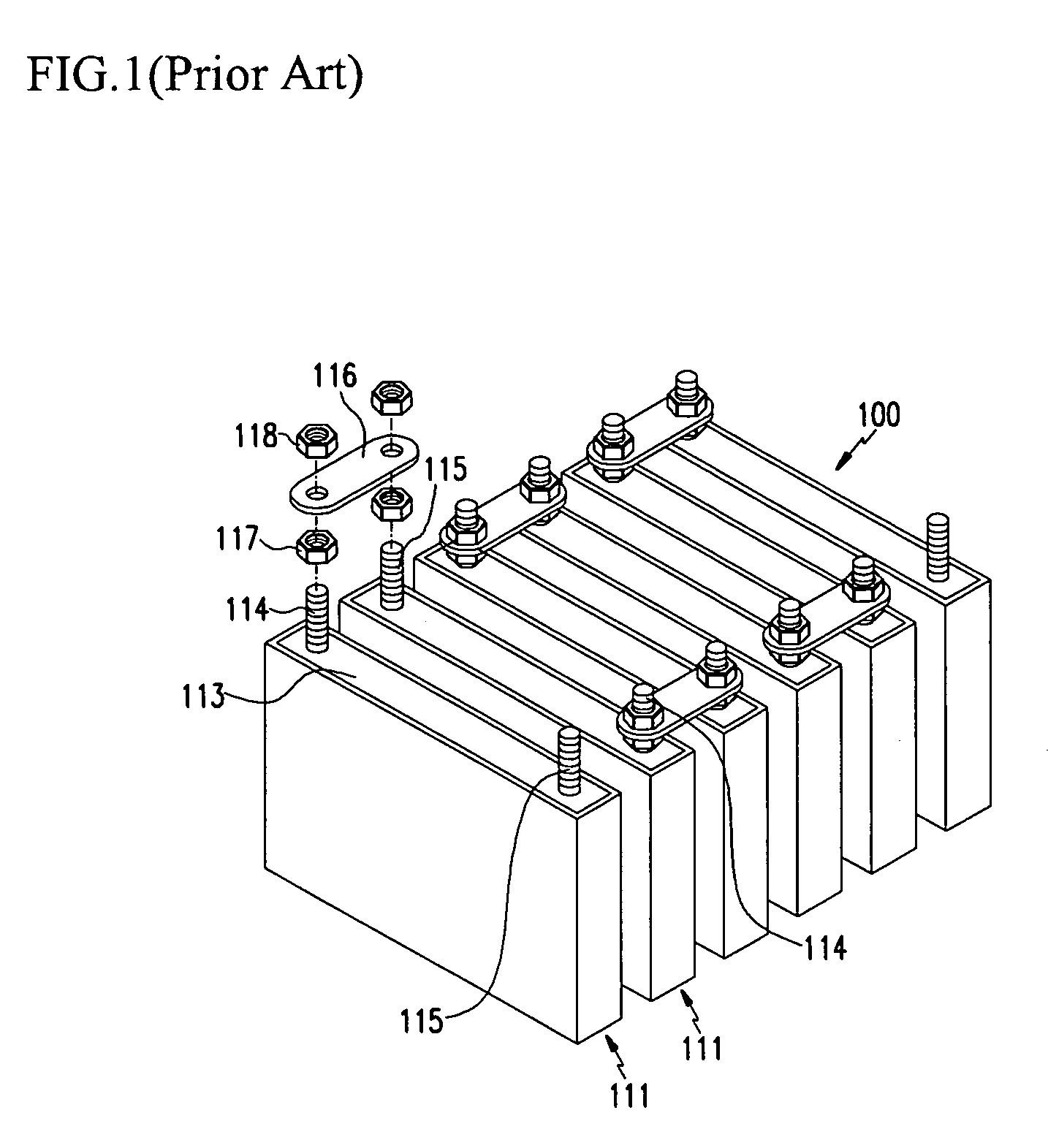
However, this conventional structure of a battery module has a problem of decreasing current collecting efficiency due to strong connection resistances between terminals and a connector.
In other words, since electrons mainly move through the nuts screwed on the terminals to a connector, the passage for electron movement is limited to the small contact area between a nut and a terminal, thus increasing connection resistances and resultantly, decreasing electric conductivity.
Especially, when a secondary battery with large capacity requires high power for driving a motor used for a hybrid electric vehicle (HEV) or an electric vehicle (EV), the aforementioned conventional art cannot establish the desired motor operation characteristics, because the increase of resistances and decrease of electric conductivity cause the decrease of power.

Method used


Image

  • Secondary battery and a secondary battery module using the same
  • Secondary battery and a secondary battery module using the same
  • Secondary battery and a secondary battery module using the same

Examples


Embodiment Construction

[0031] Referring to FIG. 2, each unit cell 11 forming a battery module 10 with large capacity includes an electrode assembly 18 including positive and negative electrodes and a separator interposed therebetween, a case 12 with a space for housing the electrode assembly, a cap assembly 13 connected with and sealing the case 12, and positive and negative terminals 14, 15 electrically connected respectively to positive and negative current collectors and protruding outward from the cap assembly 13.

[0032] The above case 12 is made of conductive metals such as aluminum, aluminum alloy, or nickel-plated steel, and its shape can be a hexagon or cylinder with an internal space for housing an electrode assembly.

[0033] According to this embodiment of the present invention, each unit cell 11 has a cap assembly 13 with two positive and negative terminals 14, 15 protruding therefrom at an interval, which will be regarded as an example of a unit cell in the below illustration.

[0034] Each unit ...


PUM


Abstract

A secondary battery module includes a connector, which electrically connects a first unit battery to an adjacent unit battery. The connector is connected to the first battery through a connecting member, which is connected to a terminal of the first battery. The connecting member has external threads and a flange on which the connector is positioned. The connector is also fitted to the connecting member and fixed thereto through a nut, which is joined with the external threads of the connecting member.

Description

CROSS REFERENCE TO RELATED APPLICATION [0001] This application claims priority to and the benefit of Korean patent application No. 10-2004-0086600 filed in the Korean Intellectual Property Office on Oct. 28, 2004, the entire disclosure of which is incorporated herein by reference. FIELD OF THE INVENTION [0002] The present invention relates to a secondary battery and more particularly, to a secondary battery with an increased current collecting efficiency by improving the connecting structure between unit cells in the battery with high power and large capacity and to a secondary battery module using the same. BACKGROUND OF THE INVENTION [0003] Recently, high power secondary batteries using non-aqueous electrolytes with high energy density have been developed. These high power secondary batteries with large capacity, which are used for electric machinery requiring large electric power for example, electric vehicles, are formed by connecting a plurality of single batteries in series. [...

Claims


Application Information

Patent Timeline
Patent Type & Authority Applications(United States)
IPC IPC(8): H01R3/00
CPCH01R11/288H01M50/209H01M50/553H01M50/505H01M50/517H01M50/55H01M50/176H01M50/188H01M50/50H01M10/0413
Inventor KIM, JAE-KYUNGSONU, JUNKIM, KI-HO
Owner SAMSUNG SDI CO LTD
Learn More