
Mobile communication terminal test system capable of visually recognizing communication condition and response signal

a mobile communication terminal and test system technology, applied in the field of test systems, can solve problems such as the difficulty of operators grasping timing relationships

Inactive Publication Date: 2006-05-04
ANRITSU CORP
View PDF3 Cites 34 Cited by
  • Summary
  • Abstract
  • Description
  • Claims
  • Application Information

AI Technical Summary

Benefits of technology

[0037] An object of the present invention is to provide a test system for a mobile communication terminal in which, in a connection transition test by a system simulator of a mobile communication terminal, a response state of a message a

Problems solved by technology

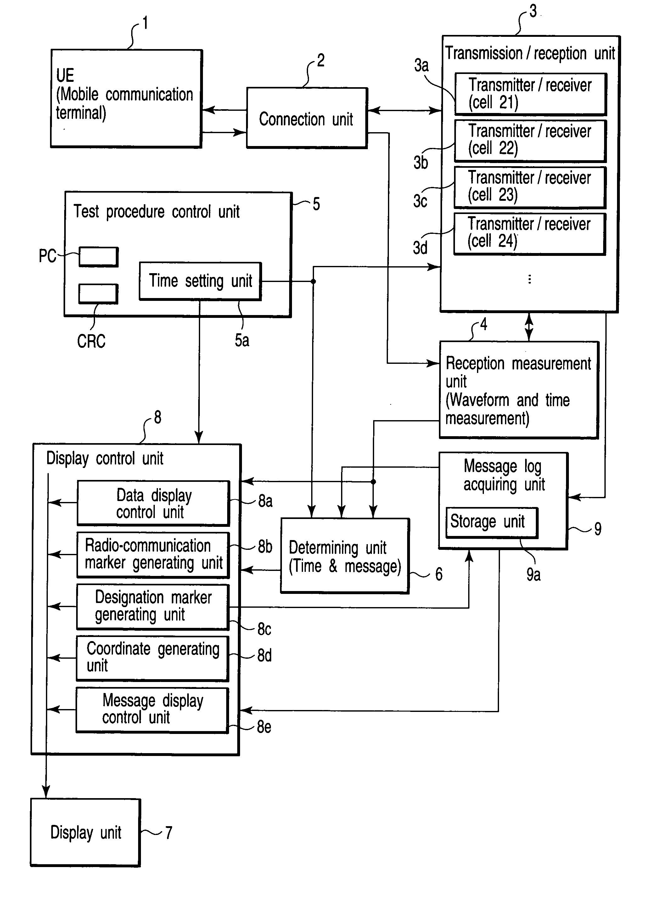
Accordingly, in the prior art, there is the problem that, when the mobile communication terminal (UE) 1 responds abnormally at a time different from a normal time, or when there is abnormality in numeric data, it is hard for an operator to grasp a timing relationship between exchanging messages and signal waveforms between the mobile communication terminal (UE) (1) and the transmission / reception unit 3 so as to be visually recognizable.

Method used


Image

  • Mobile communication terminal test system capable of visually recognizing communication condition and response signal
  • Mobile communication terminal test system capable of visually recognizing communication condition and response signal
  • Mobile communication terminal test system capable of visually recognizing communication condition and response signal

Examples


Embodiment Construction

[0121] Hereinafter, one embodiment of a test system for a mobile communication terminal according to the present invention will be described with reference to the drawings.

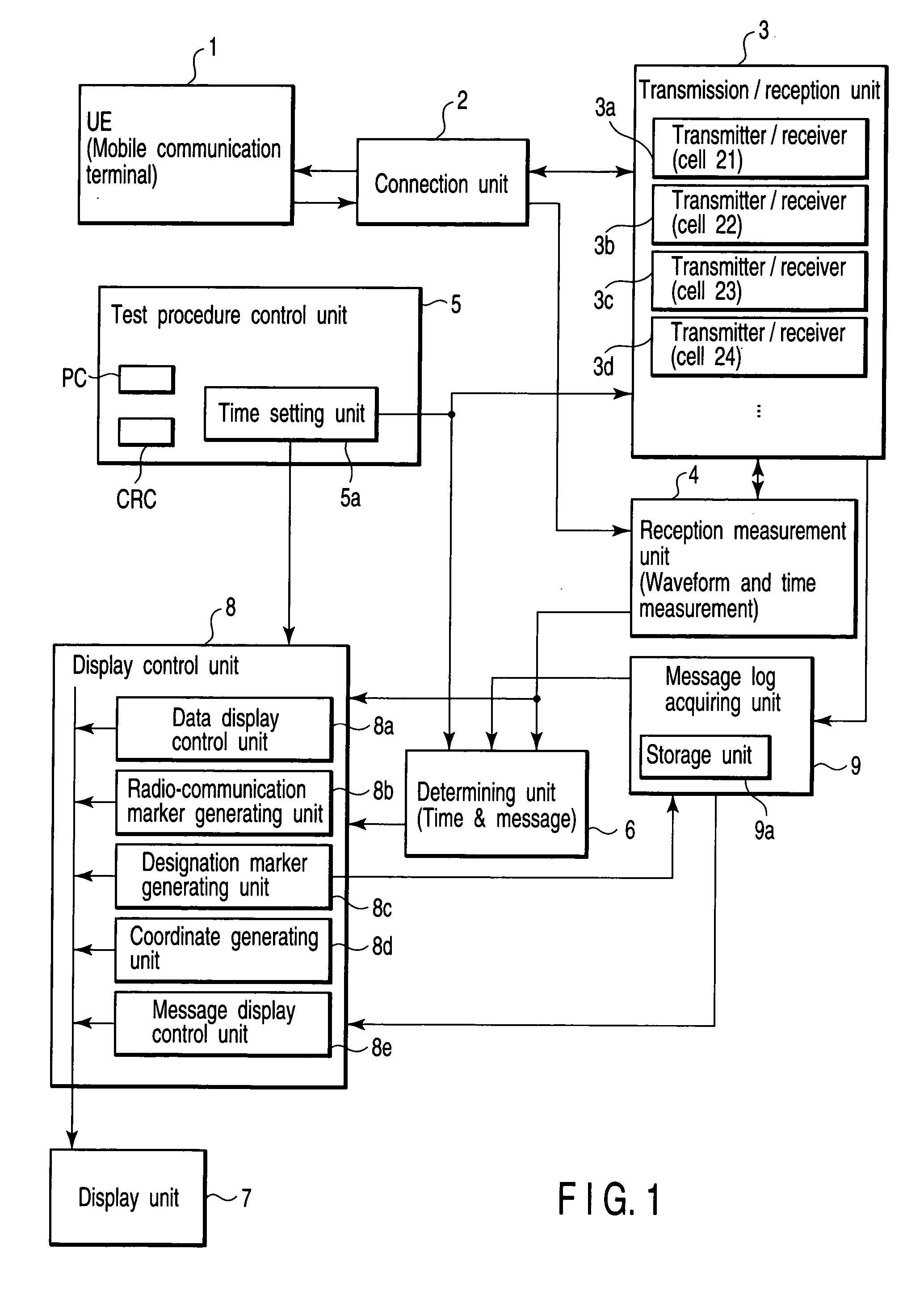
[0122]FIG. 1 is a block diagram showing a functional configuration of the test system for the mobile communication terminal according to the invention.

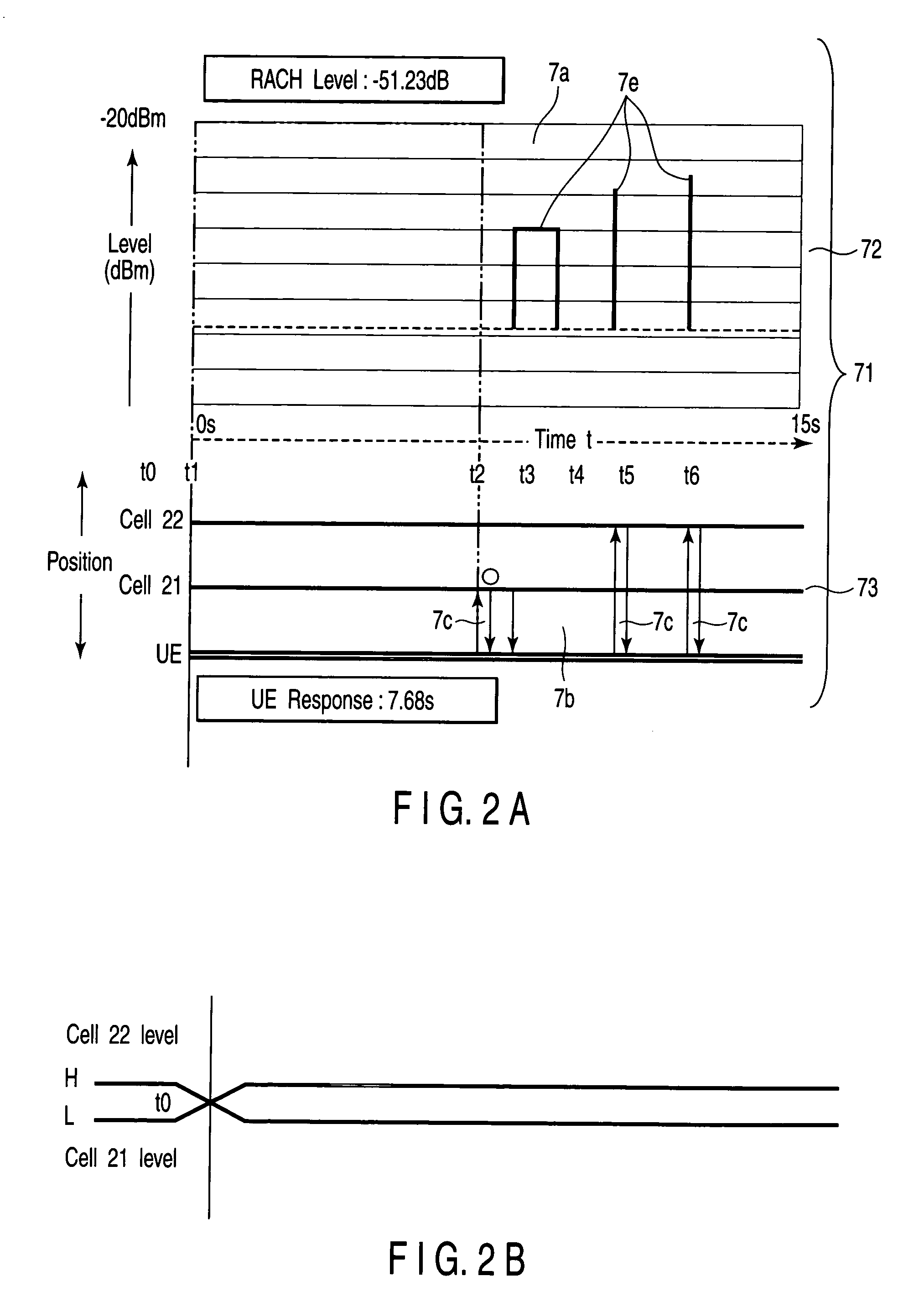
[0123]FIG. 2A is a view for explaining an example in which radio-communication states of messages between a mobile communication terminal (UE) 1 and cells 21 and 22, and waveforms of response signals from the mobile communication terminal (UE) 1 at that time, are displayed as one example of a display by a display control unit of FIG. 1.

[0124]FIG. 2B is a view for explaining transmitting power levels between the cells 21 and 22 of FIG. 2A.

[0125]FIG. 3 is a view for explaining an example in which radio-communication states of messages between the mobile communication terminal (UE) 1 and the cells 21 and 22, and waveforms of response signals from the mobile communi...


PUM


Abstract

A test procedure control unit outputs control information including time setting information in order to carry out a transition test of a connection state of a mobile communication terminal of a cellular system. In accordance with the control information, a transmission / reception unit generates a plurality of test signals including predetermined messages which correspond to a plurality of cells, and vary those in accordance with a scheduled time passage to thereby transmit those to the mobile communication terminal and receive response signals including predetermined messages from the mobile communication terminal. A reception measurement unit measures time domain waveforms of the response signals, and a message log acquiring unit acquires and stores messages and radio-communication time information when the transmission / reception unit and the mobile communication terminal exchange the respective predetermined messages. A display control unit causes to display graphs indicating measured results of the time domain waveforms and a predetermined number of radio-communication markers indicating points in radio-communication time which correspond to the radio-communication time information by a graphic display capable of simultaneously comparing at both sides of the same time base on a display unit.

Description

TECHNICAL FIELD [0001] The present invention relates to a test system for a mobile communication terminal having a system simulator function capable of communication connection with a mobile communication terminal, the test system testing, by means of a mobile communication terminal of a cellular system which moves among cells (units of service areas of respective base stations), whether or not the connection state of the mobile communication terminal appropriately transits between the cells so as to correspond to a movement of the mobile communication terminal between the cells. In particular, the invention relates to a test system for a mobile communication terminal using a technology in which an operator can visually recognize the radio-communication state in a connection transition test for switching a mobile communication terminal which is a test object to being in a receiving state by being made to simulate a transition between cells, and a response signal from the mobile comm...

Claims


Application Information

Patent Timeline
IPC IPC(8): H04Q7/20H04B7/26H04B17/00H04B17/10H04B17/15H04B17/23H04B17/29H04W24/00
CPCH04W24/06H04W72/12
Inventor ENDO, TAKAHARAONUKI, MAKOTO
Owner ANRITSU CORP
Learn More