Stand-alone scanning laser device

a laser light and laser light technology, applied in the field of medical and chiropractic devices, can solve the problems of large number of laser diodes, large mechanical requirements to achieve a rotating helmet, and devices that use relatively high-level laser energy, and achieve the effect of stimulating hair growth and low level

Active Publication Date: 2006-05-04
ERCHONIA CORP
View PDF62 Cites 46 Cited by
  • Summary
  • Abstract
  • Description
  • Claims
  • Application Information

AI Technical Summary

Benefits of technology

[0014] The present invention is a stand-alone laser device that provides low level laser therapy using one or more laser sources. The laser sources are attached to one or more arms which can be positioned to cause the laser light to impinge on a desired area of a patient's body. A scanning apparatus is attached to the arms which comprise structures that cooperate to cause an optical element to be able to simultaneously rotate about a central axis and move in a linear motion along that axis to achieve any desired scan pattern. Laser light of different pulse widths, different beam shapes and different scan patterns can be applied externally to a patient's body. In the preferred embodiment, red light having a wavelength of about 635 nm is used to stimulate hair growth on a patient's scalp.

Problems solved by technology

These devices use relatively high-level laser energy, however, to thermally destroy offending hair follicles.
A major drawback of this invention is the mechanical requirements to achieve a rotating helmet.
Another drawback is the cost of using a large number of laser diodes.
In addition to the discomfort of wearing a helmet repeatedly for extended periods, this device suffers the disadvantage of requiring many LED's to treat the scalp and limiting treatment areas to specific geometries, which can result in uneven hair growth.
However, because each treatment is relatively long and many treatments are required, it is difficult to use a hand-held laser.
The user's arm gets tired holding the laser for the required amount of time.
This limits the precision and duration of the treatment.
Neither of the devices provides a means for varying the shape or size of the beam spot on demand, nor for automatically varying the resultant intensity.
It has recently been discovered that overlapping areas of treatment can increase the effects of the therapy.
This has the disadvantage of requiring the therapist to continuously attend the patient, as well as limiting the precision and duration of the treatment.

Method used


Image

  • Stand-alone scanning laser device
  • Stand-alone scanning laser device
  • Stand-alone scanning laser device

Examples


Embodiment Construction

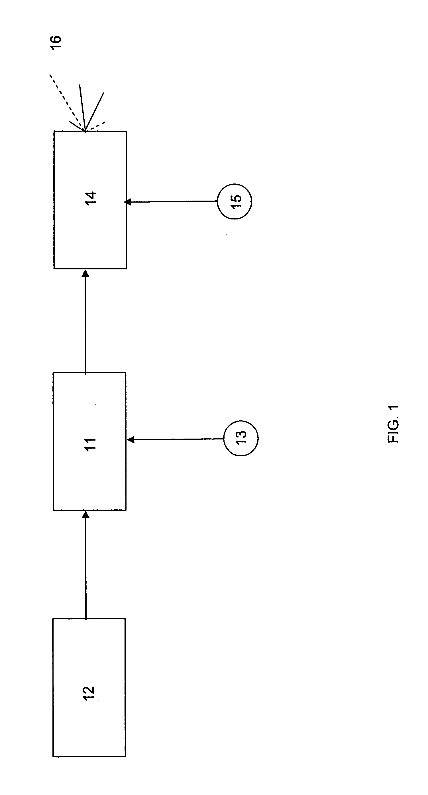
[0027]FIG. 1 illustrates a schematic of a laser device that includes a power source 12, at least one laser energy source 11, a laser control 13, a scanning head 14, and a scanner control 15. In the preferred embodiment, the laser control 13 and scanner control 15 are incorporated into a control means 17. The power source preferably provides direct current, such as that provided by a battery, but may instead provide alternating current such as that provided by conventional building outlet power (120V) that is then converted to direct current. The power supply 12 may be housed with the scanning head 14 or may be deployed separately with an electrical cable joining it thereto. Laser control 13 is connected to the laser energy source 11 and acts as on / off switch to control the period of time the laser light is generated and may also have other functions, such as controlling the pulse repetition rate. Other functions of the laser control 13, scanner control 15, and control means 17 are m...


PUM


Abstract

A stand-alone laser device that provides low level laser therapy using one or more laser sources. The laser sources are attached to one or more arms which can be positioned to cause the laser light to impinge on a desired area of a patient's body. A scanning apparatus is attached to the arms which comprise structures that cooperate to cause an optical element to be able to simultaneously rotate about a central axis and move in a linear motion along that axis to achieve any desired scan pattern. Laser light of different pulse widths, different beam shapes and different scan patterns can be applied externally to a patient's body. In the preferred embodiment, red light having a wavelength of about 635 nm is used to stimulate hair growth on a patient's scalp

Description

CROSS-REFERENCE TO RELATED APPLICATIONS [0001] This application claims the benefit of co-pending U.S. application Ser. No. 10 / 772,738 filed Feb. 4, 2004.FIELD OF INVENTION [0002] This invention relates generally to medical and chiropractic devices that employ lasers. More particularly, this invention relates to a stand-alone laser light device that scans a desired area of a patient's body. BACKGROUND [0003] Low energy laser therapy (LLLT) is used in the treatment of a broad range of conditions. LLLT improves wound healing, reduces edema, and relieves pain of various etiologies, including the treatment and repair of injured muscles and tendons. LLLT is also used during liposuction procedures to facilitate removal of fat by causing intracellular fat to be released into the interstice and post-operatively to reduce inflammation and pain. [0004] LLLT utilizes low level laser energy, that is, the treatment has a dose rate that causes no immediate detectable temperature rise of the treate...

Claims


Application Information

Patent Timeline
Patent Type & Authority Applications(United States)
IPC IPC(8): A61N5/06
CPCA61B2018/2085A61N5/0617A61N2005/0642A61N2005/067A61B2018/20351A61B2018/20355A61B2018/20359A61N5/067
Inventor SHANKS, STEVEN C.TUCEK, KEVIN B.
Owner ERCHONIA CORP
Why Eureka
Try Eureka