Channel tapping in a near-video-on-demand system

a technology of video-on-demand and channel tapping, which is applied in the field of channel tapping, can solve the problems of waste of broadcast receiver reception capacity, and achieve the effect of improving response tim

Inactive Publication Date: 2006-05-04
KONINKLIJKE PHILIPS ELECTRONICS NV
View PDF4 Cites 14 Cited by
  • Summary
  • Abstract
  • Description
  • Claims
  • Application Information

AI Technical Summary

Benefits of technology

[0005] It is an object of the invention to provide a near-video-on-demand broadcast system using a Pagoda-like broadcasting protocol that provides a better response time.

Problems solved by technology

The inventors have realized that in the conventional Pagoda schedule reception capacity of the broadcast receiver is wasted.

Method used


Image

  • Channel tapping in a near-video-on-demand system
  • Channel tapping in a near-video-on-demand system
  • Channel tapping in a near-video-on-demand system

Examples


Embodiment Construction

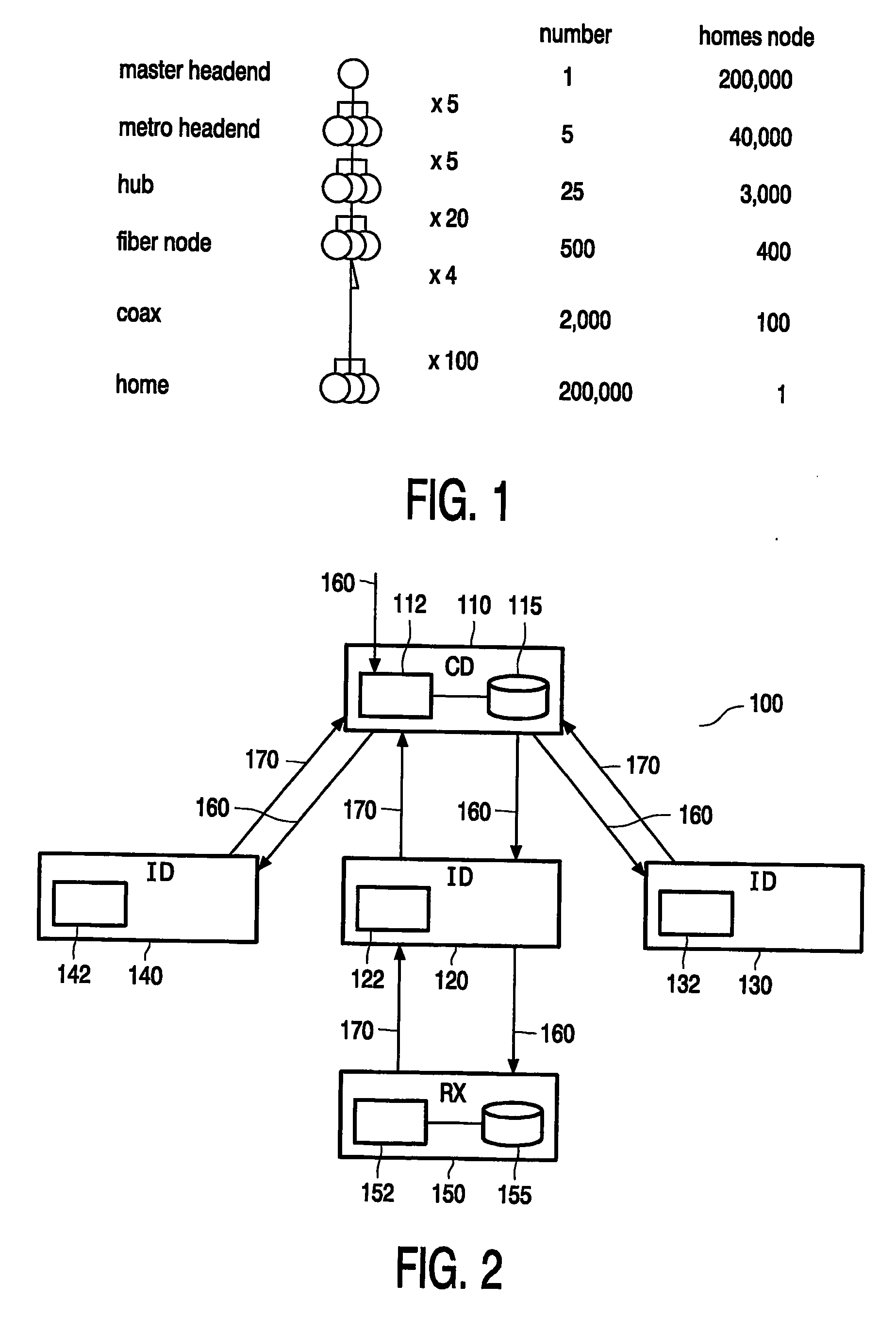
[0018]FIG. 2 shows a block diagram of the broadcast system in which the near-video-on-demand (NVoD) protocol according to the invention may be employed. The exemplary broadcast system 100 includes a hierarchical network of data distributors. The top of the network is formed by a central distributor 110. The system includes at least one layer of intermediate distributors. To simply the figure, only one intermediate layer for downstream broadcasting is shown with three intermediate distributors 120, 130 and 140, each covering a disjoint geographical area. FIG. 1 shows a typical hierarchical network for a town of 200,000 connected homes, with four intermediate downstream layers (metro headend, hub, fiber node, coaxial headend). FIG. 2 also indicates the downstream path 160 that starts at the central distributor 110, runs through the intermediate distributors 120, 130 and 140 and ends at the plurality of broadcast receivers of the system. Conventionally the distributors split the broadc...


PUM


Abstract

In a broadcast system 100 a broadcasting device broadcasts titles using a near-video-on-demand broadcasting protocol. Data blocks of a title are broadcast via c parallel equal capacity channels of the broadcast system. The broadcast channels 160 including time-sequentially interleaved sub-channel(s). The title is divided in a plurality of consecutive data block sequences. Each block sequence is assigned to one respective sub-channel. The broadcasting device repeatedly broadcasts each block sequence in the assigned sub-channel. The broadcast receiver 150 has a capacity to simultaneously receive all sub-channels of a plurality r (1i, the receiver terminates reception of the sub-channel in channel i and starts reception of at least one sub-channel of channel r+i.

Description

FIELD OF THE INVENTION [0001] The invention relates a broadcast system for broadcasting data streams to a plurality of broadcast receivers through a communication system. The invention further relates to a broadcast receiver for use in such a system. The invention also relates to a method of receiving a broadcast title. BACKGROUND OF THE INVENTION [0002] Conventional digital broadcasting systems, such as cable networks, terrestrial broadcast networks or satellite networks, have a capacity in the order of one gigabit per second downstream (i.e. in the direction from a central broadcaster towards the broadcast receiver). Some of this capacity is reserved for conventional broadcast channels, like the most popular television stations. Such channels can in principle be received by all broadcast receivers (i.e. it is transmitted via all coax cables), although actual receipt may be conditional upon payment. A small part of the bandwidth may be reserved for upstream communication from the b...

Claims


Application Information

Patent Timeline
Patent Type & Authority Applications(United States)
IPC IPC(8): H04N7/173
CPCH04N7/17318H04N21/26275H04N21/8456H04N21/266H04N21/643
Inventor VERHAEGH, WILHELMUS FRANCISCUSRIETMAN, RONALDKORST, JOHANNES HENRICUS MARIA
Owner KONINKLIJKE PHILIPS ELECTRONICS NV
Why Eureka
Try Eureka