Spinning device and method for detecting fiber accumulated state

a technology of accumulating state and spinning device, which is applied in the direction of yarn, open-end spinning machine, textiles and paper, etc., can solve the problems of increasing the size of the spinning device, not always sufficiently effective in preventing, and yarn deformation, so as to achieve easy and reliable determination

Inactive Publication Date: 2006-05-11
MURATA MASCH LTD
View PDF3 Cites 13 Cited by
  • Summary
  • Abstract
  • Description
  • Claims
  • Application Information

AI Technical Summary

Benefits of technology

[0020] This makes it possible to easily and reliably determine whether or not fibers ha

Problems solved by technology

This causes a defect in the yarn (what is called a weak yarn).
Accordingly, the above configuration is not alway

Method used


Image

  • Spinning device and method for detecting fiber accumulated state
  • Spinning device and method for detecting fiber accumulated state
  • Spinning device and method for detecting fiber accumulated state

Examples


Embodiment Construction

[0026] A preferred embodiment of the present invention will be described below with reference to the accompanying drawings.

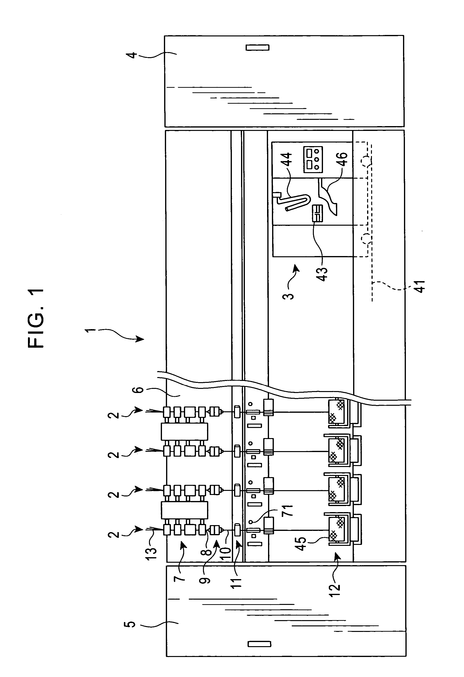
[0027]FIG. 1 shows a spinning device 1 according to an embodiment of the present invention. The spinning device 1 comprises a large number of spinning units 2 arranged in a line. The spinning device 1 is provided with a yarn splicing carriage 3, a blower box 4, and a motor box 5. The yarn splicing carriage 3 can run in the direction in which the spinning units 2 are arranged.

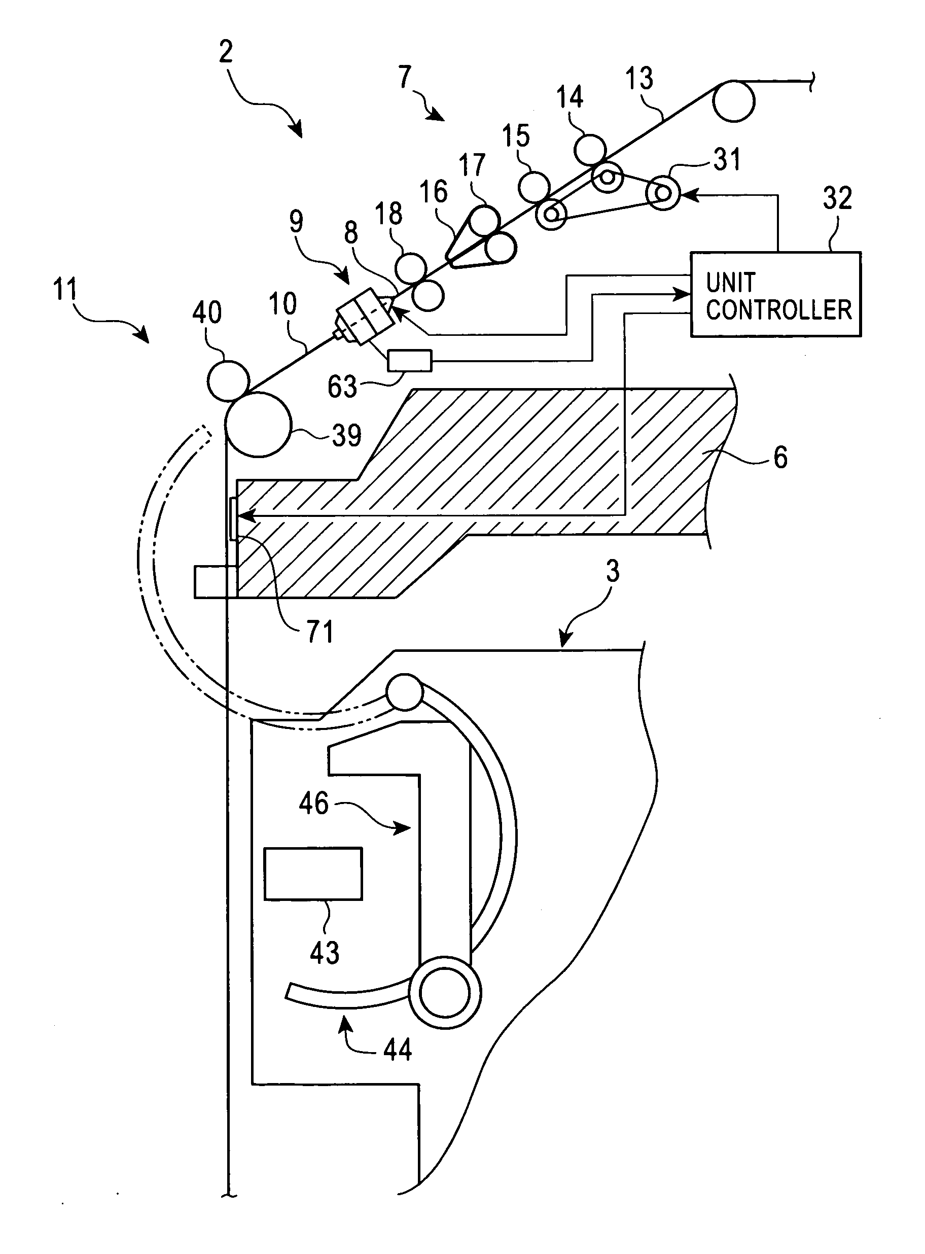
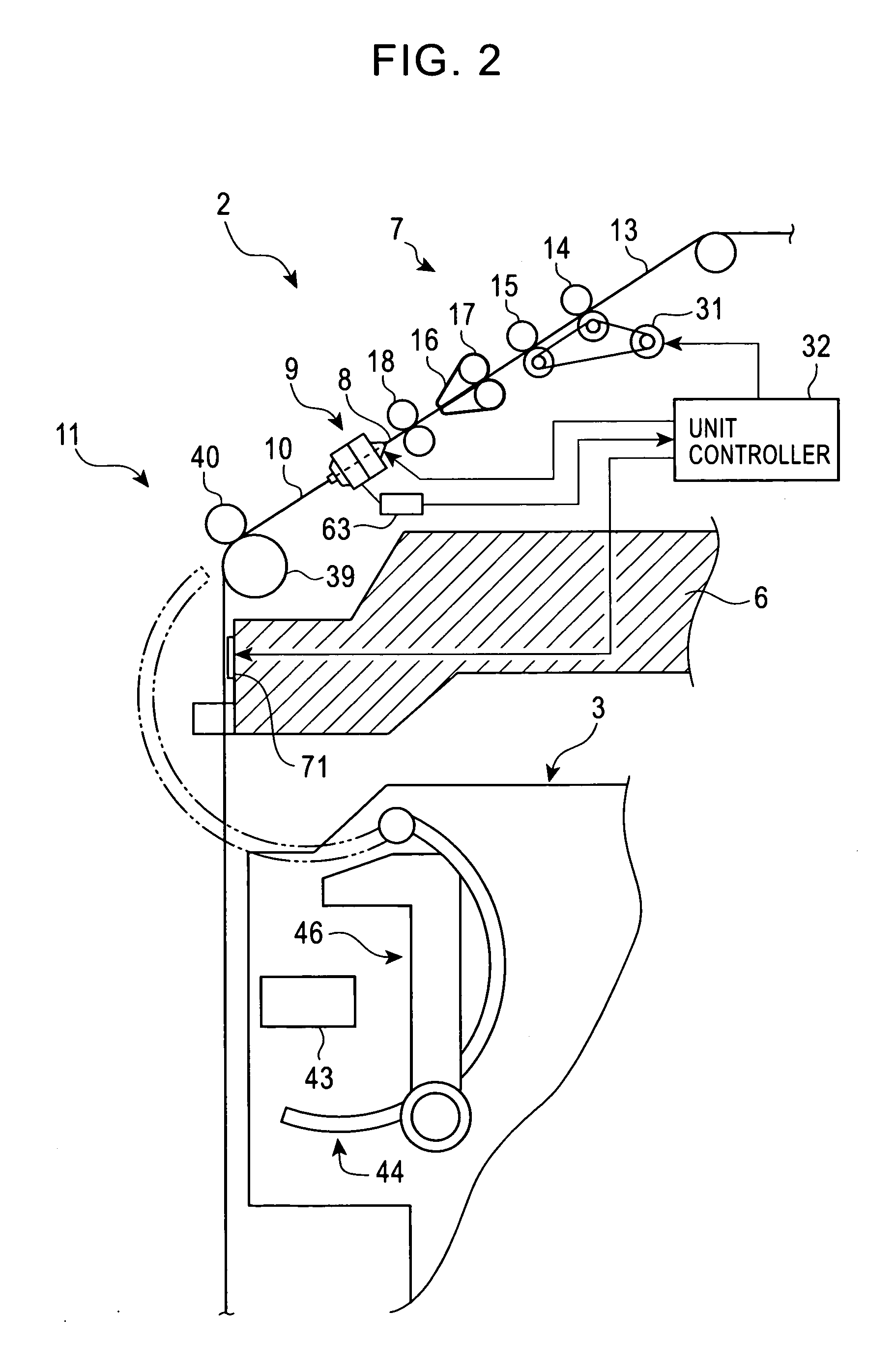
[0028] As shown in FIG. 1, each spinning unit 2 is mainly composed of a draft device 7, a spinning section 9, a yarn feeding device 11, and a winding device 12. The draft device 7 is provided near an upper end of a casing 6 of the spinning device 1 main body. The spinning section 9 spins a bundle of fibers 8 fed by the draft device 7. The yarn feeding device 11 feeds a spun yarn 10 discharged by the spinning section 9. The winding device 12 then winds the spun yarn 10 to form a package 45....


PUM

PropertyMeasurementUnit
Pressureaaaaaaaaaa

Abstract

It is an object of the present invention to provide a spinning device that detects early that fibers F have been accumulated in an air exhausting space 55 to prevent a defect (weak yarn) in a spun yarn. A spinning device in accordance with the present invention includes a pneumatic spinning nozzle 19, a whirling current generating chamber 25 in which fibers are twisted using a whirling air current generated by the pneumatic spinning nozzle, an air exhausting space 55 that is in communication with the whirling current generating chamber 25, a negative pressure source that sucks air from the air exhausting space 55, and a pressure sensor 63 that detects a pressure in the air exhausting space 55. When the pressure detected by the pressure sensor 63 during a spinning operation performed by the pneumatic spinning nozzle 19 rises to at least a predetermined value, the unit controller 32 performs control such that the spinning operation is stopped. The unit controller 32 further lights an alarm lamp 71.

Description

FIELD OF THE INVENTION [0001] The present invention relates to the configuration of a spinning device, and in particular, to a configuration that can easily sense a state in which a spun yarn is likely to become defective. BACKGROUND OF THE INVENTION [0002] The Unexamined Japanese Patent Application Publication (Tokkai-Hei) No. 2001-192938 discloses a spinning device that spins a yarn by opening a bundle of fibers using a whirling air current generated by a pneumatic spinning nozzle and twisting the fibers while winding them around the periphery of a tip portion of a hollow guide shaft. In this configuration, an air exhausting space is in communication with a hollow chamber in the tip portion of the hollow guide shaft. A whirling air current generated by the pneumatic spinning nozzle flows from the hollow chamber to the air exhausting space, where it is exhausted. [0003] Then, the Unexamined Japanese Patent Application Publication (Tokkai-Hei) No. 2001-192938 points out the followin...

Claims


Application Information

Patent Timeline
IPC IPC(8): D01H13/26D02G3/02
CPCD01H1/115D01H4/02D01H4/42
Inventor YAMAMOTO, ATSUSHITAKAHASHI, TOMOAKIOKA, MASAKI
Owner MURATA MASCH LTD
Why Eureka
Try Eureka