
Internal combustion engine diagnostic apparatus

a technology for internal combustion engines and diagnostic equipment, which is applied in the direction of machines/engines, electrical control, instruments, etc., can solve the problems of misfire abnormalities, abnormalities that may be detected permanently, and abnormalities that may be simply dissolved

Inactive Publication Date: 2001-11-20
TOYOTA JIDOSHA KK
View PDF8 Cites 1 Cited by
  • Summary
  • Abstract
  • Description
  • Claims
  • Application Information

AI Technical Summary

Benefits of technology

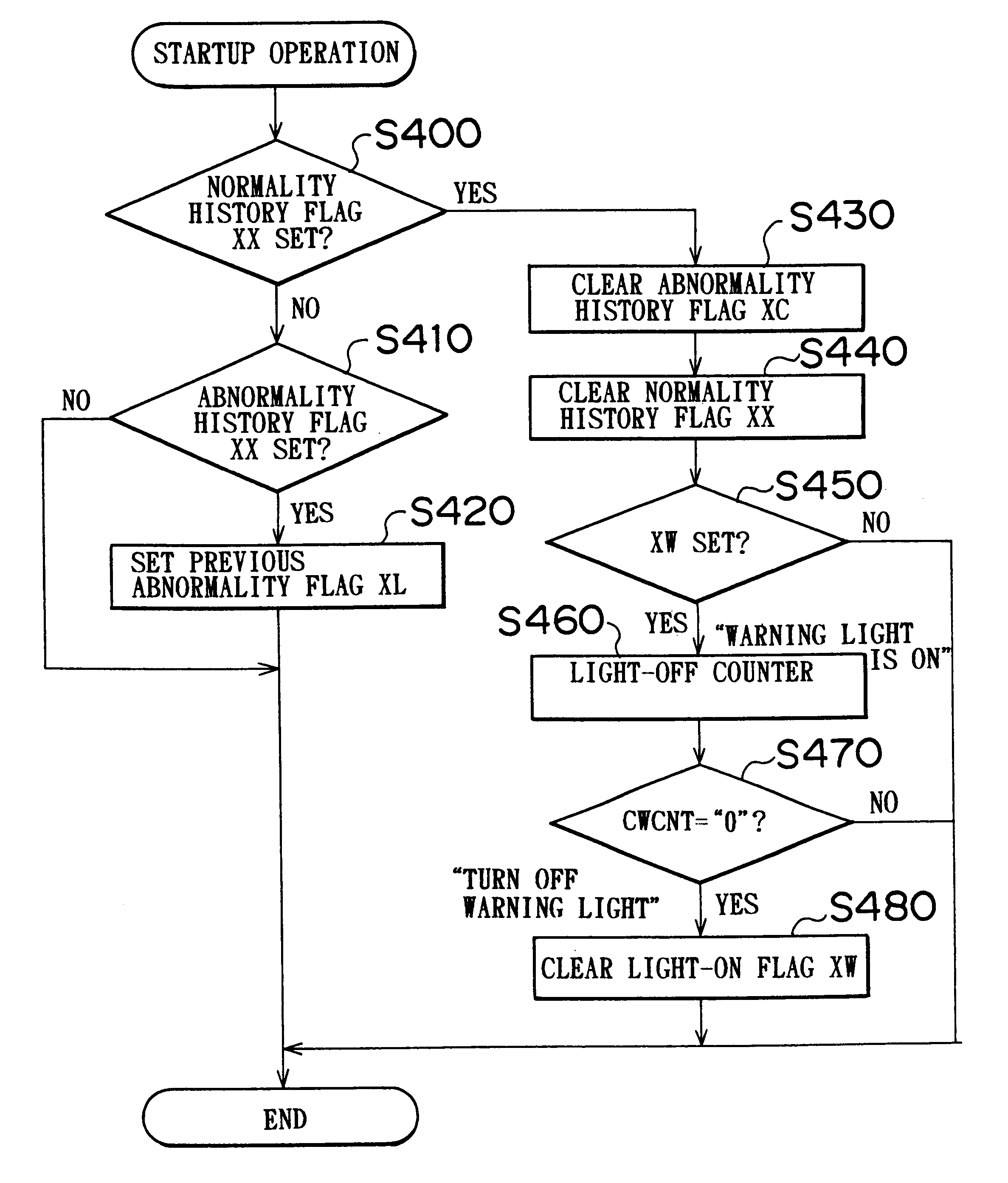
Therefore, if after the first diagnosis of the presence of an abnormality is made by the diagnostic device, the second diagnosis of the presence of an abnormality is made after a restart of the internal combustion engine, the condition management device permits the execution of the warning, so that the warning is executed. Hence, the diagnostic apparatus reduces the incidence of execution of an unnecessary or inappropriate warning in response to a temporary abnormality that does not have repeatability, for example, an abnormality that disappears merely upon a restart of the internal combustion engine. Thus, the apparatus ensures that the warning regarding an abnormality will be executed in a more appropriate manner.
With this construction, the condition management device permits the execution of the warning on the condition that when the abnormality diagnosis history is retained by the temporary retaining device (XL), that is, when the internal combustion engine has not returned to the normal state since a restart of the engine after the diagnosis of the presence of an abnormality was made by the diagnostic device, the diagnosis of the presence of an abnormality is made again by the diagnostic device. By using the contents of the histories retained by the history retaining devices and the abnormality diagnosis history retaining device as a basis, it becomes possible to easily and reliably determine whether the condition for permitting the execution of the warning is met and, therefore, it becomes possible to more appropriately execute the warning.

Problems solved by technology

Although it is important to notify a driver of any detection of abnormality, it is not always the case that the detected abnormality needs urgent treatment; nor is the detected abnormality necessarily permanent.
Therefore, the abnormality may simply dissolve when the engine is restarted.
Thus, even if there is no problem with the internal combustion engine, a misfire abnormality may be indicated depending on the operational condition of the engine, the operation environment, and the like.
Therefore, if a warning is given every time an abnormality is determined, as in the above-described apparatus, the incidence of inappropriate and / or unnecessary warnings will increase so that a driver may be annoyed or may become doubtful.
However, an elevated criterion will also reduce the precision of the detection of abnormalities of which the driver needs to be notified.
With this construction, in the case where after the first diagnosis of the presence of an abnormality is made by the diagnostic device, the return of the engine to the normal state is recognized by the recovery recognizing device, the condition management device does not permit the warning to be executed even if the second diagnosis of the presence of an abnormality is made by the diagnostic device after the engine is restarted.

Method used


Image

  • Internal combustion engine diagnostic apparatus
  • Internal combustion engine diagnostic apparatus
  • Internal combustion engine diagnostic apparatus

Examples


Embodiment Construction

A preferred embodiment of the internal combustion engine diagnostic apparatus of the invention will be described in detail hereinafter with reference to the accompanying drawings.

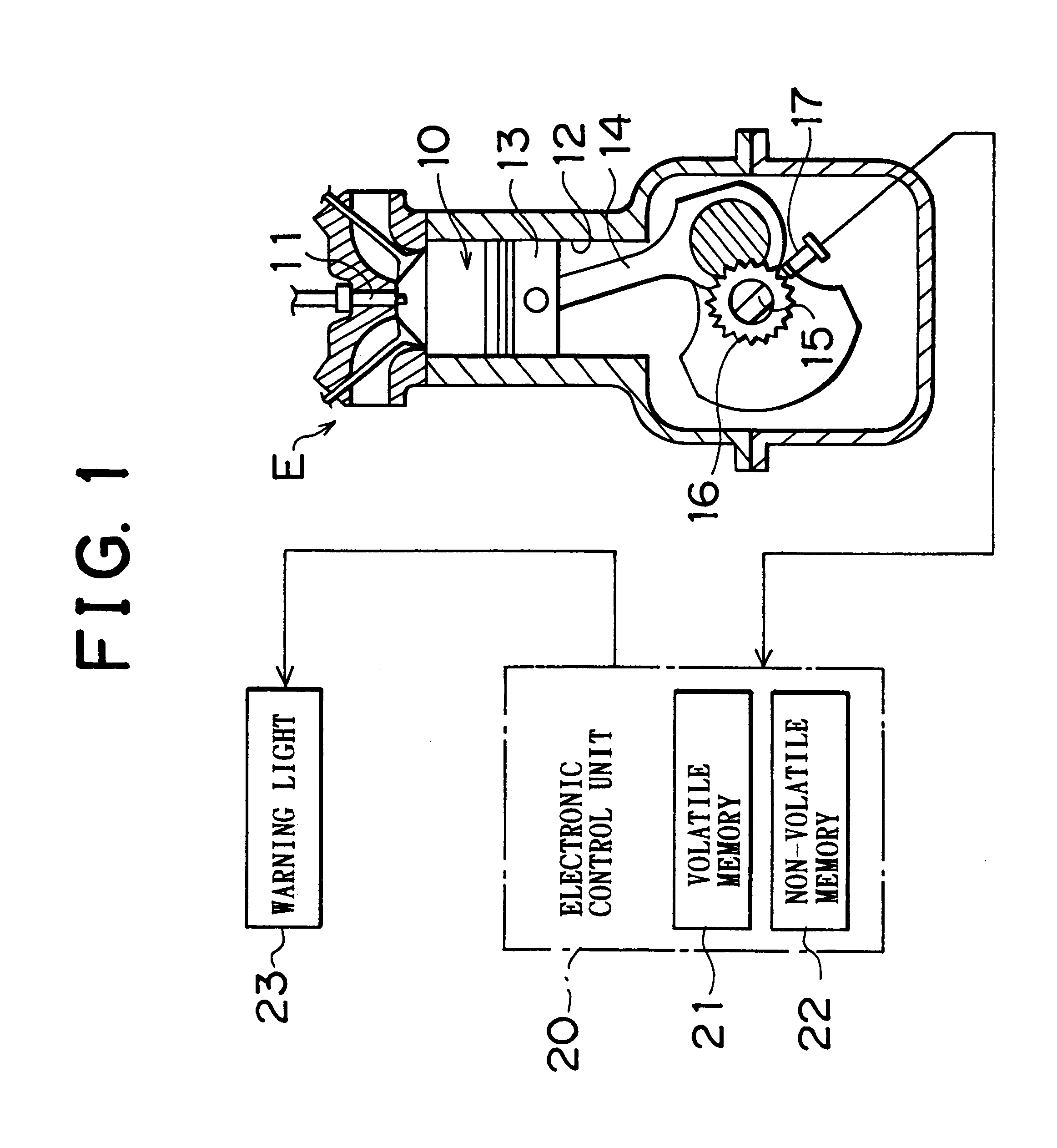
First, an internal combustion engine (vehicle engine) to which the embodiment of the diagnostic apparatus is applied will be described with reference to FIG. 1.

Referring to FIG. 1, an internal combustion engine E is a spark injection type internal combustion engine in which a spark caused by discharge from an ignition plug 11 is used to ignite a mixture introduced into a combustion chamber 10. The explosion of an ignited mixture pushes a piston 13 that is provided for reciprocating movements in a cylinder 12, thereby rotating a crankshaft 15 that is connected to the piston 13 by a connecting rod 14.

The crankshaft 15 is provided with an engine revolution speed (NE) detection rotor 16 in such a manner that the crankshaft 15 and the speed detection rotor 16 rotate together. The speed detection rotor 16 has, on...


PUM


Abstract

In a diagnostic apparatus for an internal combustion engine, an electronic control unit recognizes occurrence of a misfire in the engine based on fluctuations of the rotational speed of a crankshaft detected by a rotation speed sensor. Based on the detected incidences of misfire, the electronic control unit performs diagnostics. The electronic control unit turns on a warning light when, after the first diagnosis of the presence of an abnormality, a second diagnosis of the presence of an abnormality is made without the return of the engine to the normal state being recognized after a restart of the engine.

Description

INCORPORATION BY REFERENCEThe disclosure of Japanese Patent Application No. HEI 11-129793 filed on May 11, 1999 including the specification, drawings and abstract is incorporated herein by reference in its entirety.1. Field of the InventionThe present invention relates to a diagnostic apparatus for an internal combustion engine.2. Description of the Related ArtMany internal combustion engines, such as vehicle engines and the like, are equipped with a well known diagnostic apparatus that determine normality / abnormality of the engine and locates an abnormality if any is detected. Such a diagnostic apparatus has a self-diagnostic function, diagnosing an abnormality based on output signals of various sensors that detect operational conditions of the engine. The apparatus constantly diagnoses whether there is a failure, and performs an operation for warning a driver and / or a fail-safe operation, etc.An example of the aforementioned diagnostic apparatus described in Japanese Patent Applic...

Claims


Application Information

Patent Timeline
IPC IPC(8): F02D41/14F02P17/12G01M15/11G01M15/04F02D45/00
CPCF02D41/1495F02P17/12G01M15/11
Inventor ADACHI, SHINAMANO, HIDETOSHI
Owner TOYOTA JIDOSHA KK
Learn More