System and method for controlling engine RPM of a ducted fan aircraft

a technology of ducted fan and engine rpm, which is applied in the direction of aircraft navigation control, vertical landing/take-off aircraft, transportation and packaging, etc., can solve the problems of limiting the maximum moment that can be produced, high drag, and numerous design problems, and achieve optimal forward-speed-to-tip-speed ratio and optimal forward-speed-to-tip-speed ratio

Active Publication Date: 2006-05-11
AURORA FLIGHT SCI CORP
View PDF79 Cites 40 Cited by
  • Summary
  • Abstract
  • Description
  • Claims
  • Application Information

AI Technical Summary

Benefits of technology

[0020] According to the fifth aspect, the method can include the steps of: d.) controlling the RPM of the engine to maintain a maximum power of the engine for full-throttle flight; e.) controlling the RPM of the engine to maintain the RPM within a substantially narrow range of values; f.) controlling the RPM of the engine to operate the ducted fan at a substantially optimal forward-speed-to-tip-speed ratio of the ducted fan; g.) movably mounting a plurality of vanes on an interior of the ducted fan; h.) movably mounting a plurality of vanes on an exterior of the ducted fan; i.) movably mounting a plurality of vanes on outer corner edges of the exhaust end; j.) movably mounting a plurality of sets of vanes on outer corner edges of the exhaust end; k.) staggering the plurality of sets of vanes along the outer corner edges of the exhaust end; and l.) differentially deflecting at least one set of vanes. The at least one set of vanes can include a split at substantially a middle of a span of the at least one set of vanes. A first set of vanes can be mounted fore of a second set of vanes. A trailing edge of the first set of vanes can be substantially aligned with a hinge edge of the second set of vanes. A hinge edge of a first set of vanes on an outer corner edge of the exhaust end can be substantially aligned with a hinge edge of a second set of vanes on an adjacent outer corner edge of the exhaust end. The first and second sets of vanes can be configured to allow unobstructed deflection between the first and second sets of vanes.
[0021] According to the fifth aspect, the method can include the steps of: m.) movably mounting at least a first set of vanes on outer corner edges of the exhaust end; n.) movably mounting at least a second set of vanes within the ducted fan fore of the plurality of control surfaces near the exhaust end; o.) movably mounting at least two additional vanes within the ducted fan fore of the plurality of control surfaces near the exhaust end and substantially flush with respective interior walls of the ducted fan; p.) coupling the at least two additional vanes to the at least second set of vanes such that a trailing edge of one of the at least two additional vanes moves into an interior of the ducted fan when trailing edges of the at least second set of vanes are deflected away from the respective interior wall of the ducted fan; q.) movably mounting a plurality of vanes within the ducted fan fore of the plurality of control surfaces near the exhaust end in respective openings in walls of the ducted fan, wherein the plurality of vanes seal the openings when closed, and wherein the plurality of vanes divert air flow from inside the ducted fan to outside the ducted fan through the openings when open; and r.) actuating the plurality of vanes to control a reverse thrust of the aircraft. Step (b) can comprise the step of: s.) balancing pressure loads on the plurality of control surfaces. A duct of the ducted fan can include a substantially c...

Problems solved by technology

However, such designs suffer from numerous problems.
For example, the vanes can only redirect a fraction of the total air flow for pitch or yaw control, thus limi...

Method used


Image

  • System and method for controlling engine RPM of a ducted fan aircraft
  • System and method for controlling engine RPM of a ducted fan aircraft
  • System and method for controlling engine RPM of a ducted fan aircraft

Examples


Embodiment Construction

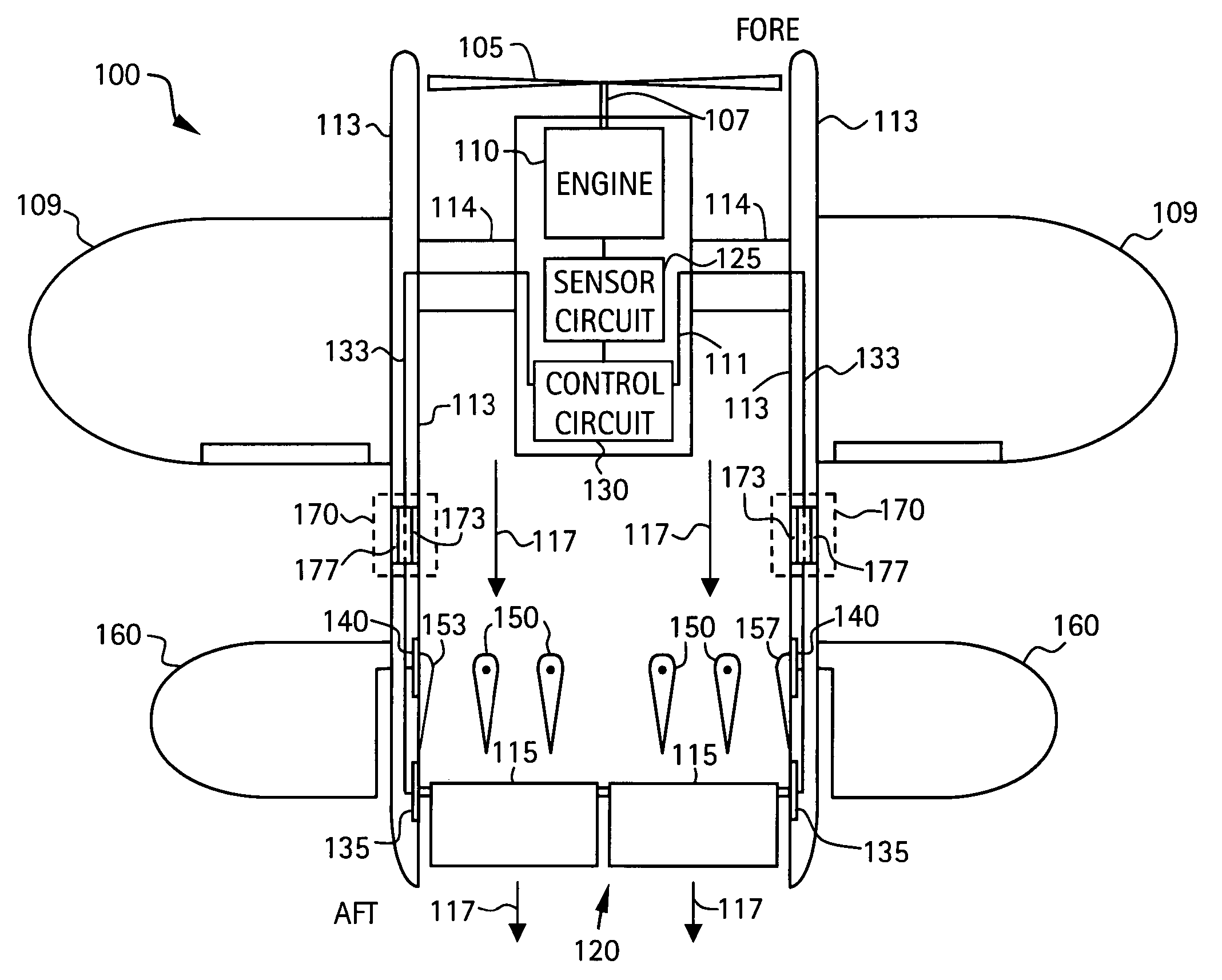
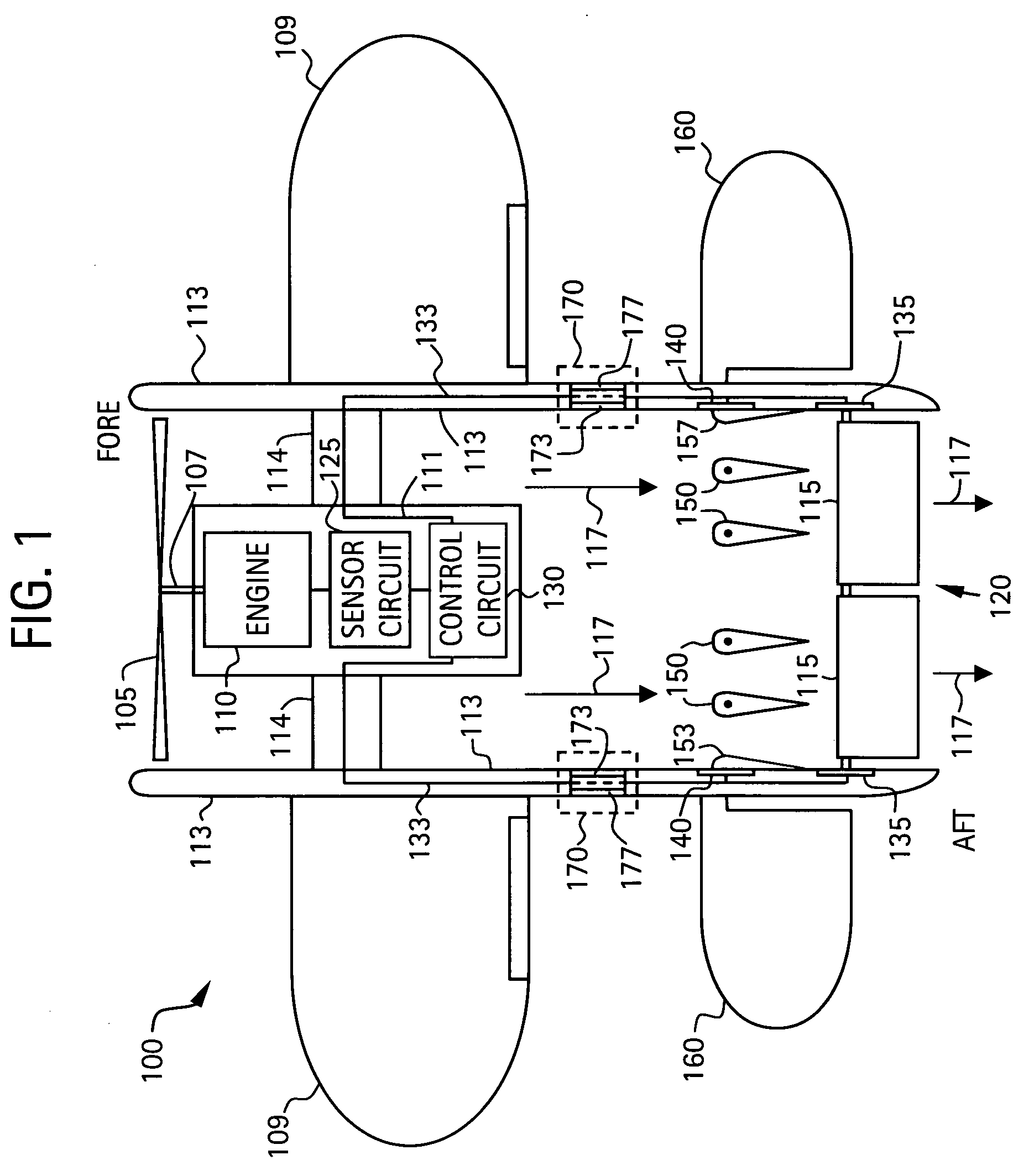
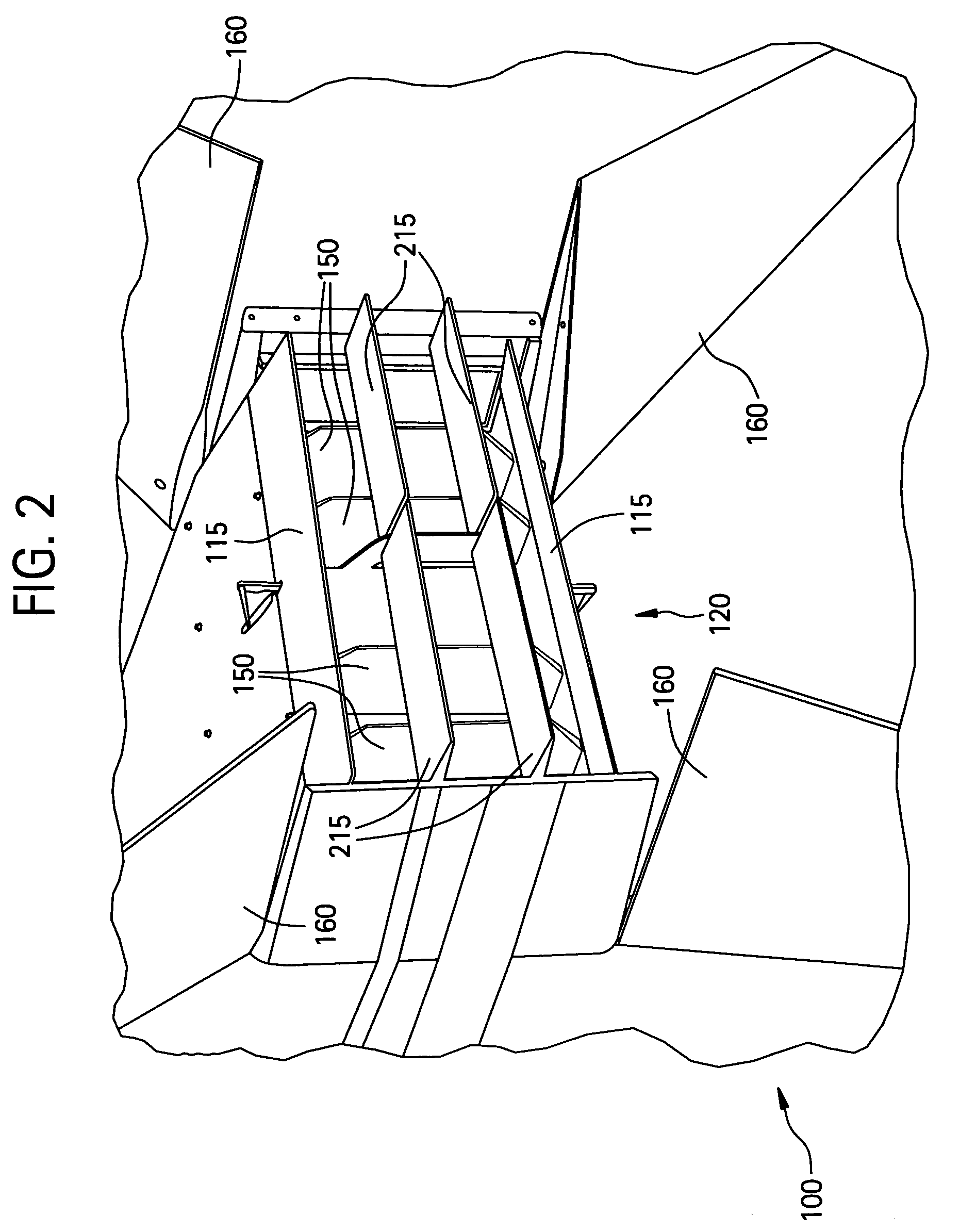
[0033] Exemplary embodiments of the present invention are directed to an aircraft that includes a ducted fan and an engine for driving the ducted fan, such as, for example, a vertical take-off and landing (VTOL) ducted fan aircraft or the like. According to exemplary embodiments, the ducted fan aircraft includes an exhaust (aft) end that can have, for example, a substantially rectangular or square cross sectional area. A plurality of vanes can be movably mounted to the ducted fan at the exhaust end. Each of the plurality of vanes can also be substantially rectangular or square in shape. Using a substantially rectangular or square exhaust nozzle and vanes, the plurality of vanes can be deflected to change the exit area of the exhaust end of the aircraft. For a ducted fan aircraft, the change in exhaust end exit area can change the air pressure load on the ducted fan. As the load on the ducted fan increases, the ducted fan can spin more slowly. As the ducted fan spins more slowly, the...


PUM


Abstract

An aircraft including a ducted fan and an engine for driving the ducted fan includes a plurality of vanes movably mounted to the aircraft at a substantially rectangular exhaust end of the aircraft. Each of the plurality of vanes is substantially rectangular or square. The plurality of vanes are configured to alter an exit area of the exhaust end. The aircraft includes a sensor circuit for detecting a RPM of the engine and for outputting a RPM signal. The aircraft includes a control circuit coupled to the sensor circuit and the plurality of vanes. The control circuit is configured to actuate the plurality of vanes to alter the exit area of the exhaust end to vary a pressure load on the ducted fan to control the RPM of the engine in response to the RPM signal.

Description

[0001] This application claims priority under 35 U.S.C. § 119(e) to U.S. Provisional Application No. 60 / 610,565, filed on Sep. 17, 2004, the entire contents of which are hereby incorporated by reference herein.BACKGROUND [0002] 1. Field of the Invention [0003] The present invention relates to ducted fan aircraft. More particularly, the present invention relates to a system and method for controlling engine RPM of a ducted fan aircraft, such as, for example, a ducted fan vertical takeoff and landing (VTOL) aircraft. [0004] 2. Background Information [0005] There have been numerous designs for vertical take off and landing (VTOL) aircraft that are powered by a single ducted fan. In such designs, the pitch, yaw and roll control moments are generated by vanes located aft of the fan, within the high-speed air flow. These vanes turn the exhaust flow about an appropriate axis to produce the required moments. In conventional designs, the vanes are grouped into two sets, each with their pivot...

Claims


Application Information

Patent Timeline
IPC IPC(8): B64B1/36
CPCB64C11/001B64C15/02B64C29/0025
Inventor PARKS, ROBERTLEDE, JEAN-CHARLESDRELA, MARK
Owner AURORA FLIGHT SCI CORP
Why Eureka
Try Eureka