Panel barriers

a technology of panels and barriers, applied in the field of panels, can solve the problems of material cracking or fracture, ceramic or glass panels that require a great deal of pressure to suspend, and the pressure required to suspend a panel generally increases with increasing weight, so as to reduce the stress force on the material and reduce the stress for

Inactive Publication Date: 2006-05-11
MCGREGOR ROBERT ROY
View PDF6 Cites 34 Cited by
  • Summary
  • Abstract
  • Description
  • Claims
  • Application Information

AI Technical Summary

Benefits of technology

[0013] Another object of the present invention is to provide a railing system which is capable of using more aesthetic panel materials while still meeting building codes.
[0014] Another object of the present invention is to provide a support system which supports and stabilizes materials while providing reduced stress force as compared to prior art support means.
[0015] It is another object of the present invention to provide a means of securing heavy panels without the necessity of modifying the panel.
[0016] It is another object of the present invention to provide a means of securing brittle panels without the necessity of modifying the panel.
[0017] It is another object of the present invention to provide support for brittle materials while reducing stress force on the material as compared to prior art devices.

Problems solved by technology

The pressure required to suspend a panel generally increases with increased weight.
Therefore, a panel made of ceramic or glass would require a great deal of pressure to suspend.
Prior art pressure clips tend to place glass and other brittle materials under such pressure that it does not take much to cause the material to crack or fracture.
Since there are building codes which require barriers to withstand certain forces without fracture before they could be used on a building, many of these systems will not meet or exceed the code making them unusable as they are designed for the uses listed above.
As described above, drilling holes in this type of material, or cutting notches causes weakened points.

Method used


Image

  • Panel barriers
  • Panel barriers
  • Panel barriers

Examples


Embodiment Construction

[0027] This invention relates to a system for holding and securing materials without the need for drilling holes in the material or cutting notches in the material. The present invention holds the material with reduced pressure as compared to the prior art.

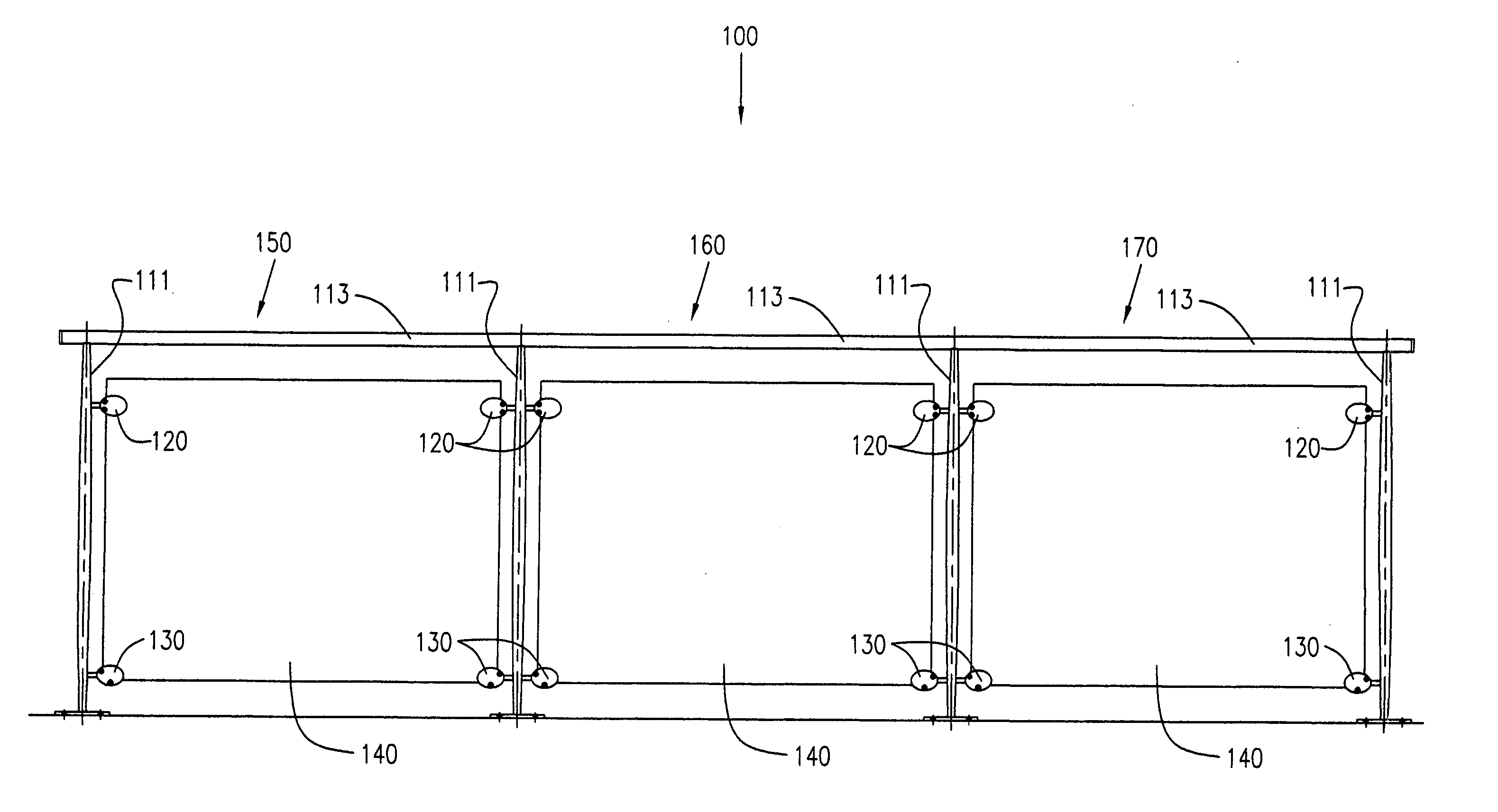
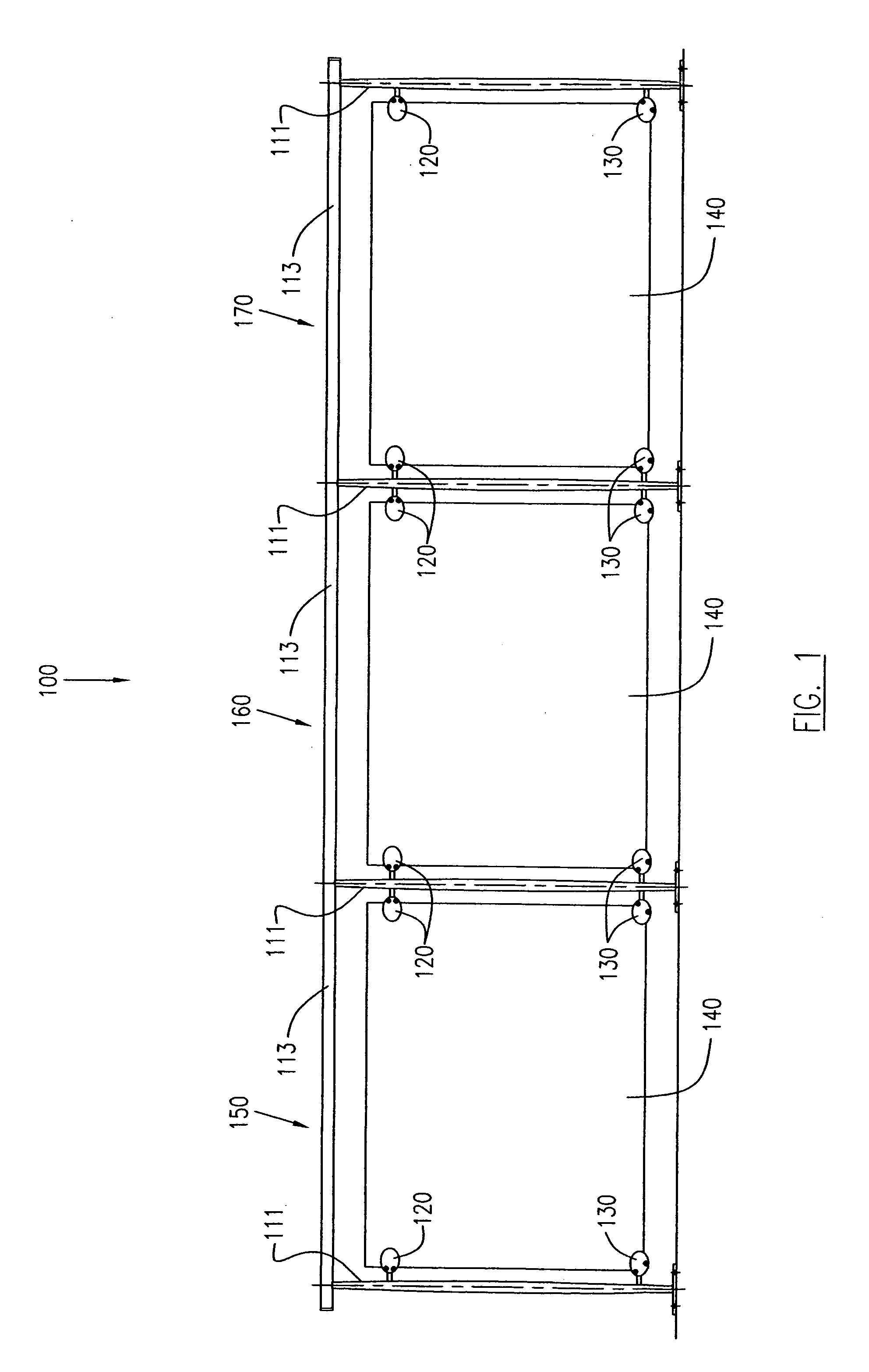
[0028]FIG. 1 is a side elevational view showing several sections 150, 160, 170 of a panel barrier system 100 according to one embodiment of the present invention. Each section in this embodiment has a frame 110 having at least one vertical member 111 and a horizontal member 113.

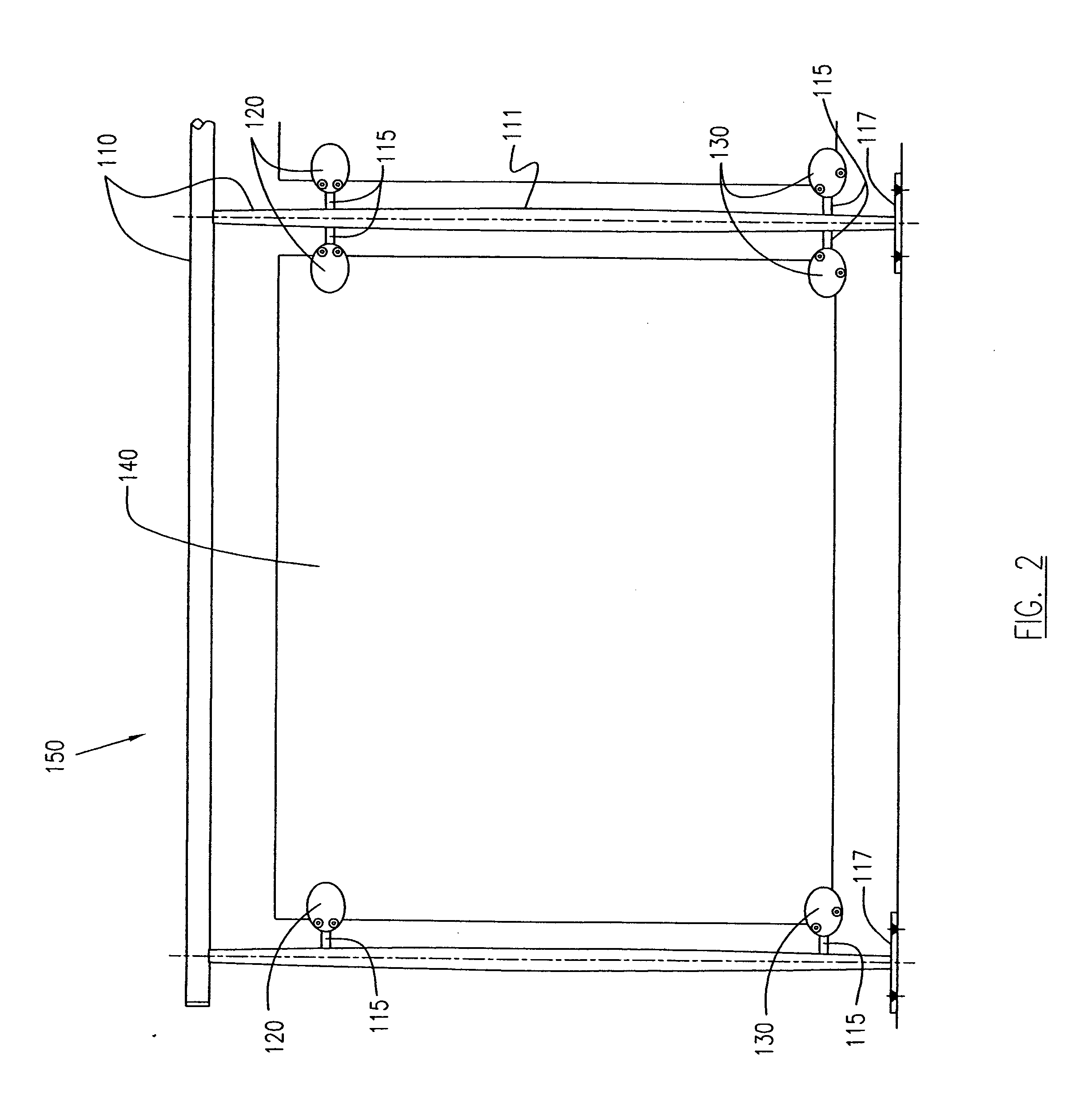
[0029] A panel 140, which may be made of various materials, is supported and stabilized within the frame 110. A plurality of connectors 115 are attached to the vertical members 111 and extend generally horizontally.

[0030] Each connector is attached to either an upper support 120, or a lower support 130. Lower supports 130 are designed to provide vertical member and hold the weight of the panels 140, while stabilizing panels 140 from moving in other direc...


PUM


Abstract

A panel barrier panel system is provided which employs aesthetically pleasing panels which tend to be brittle, but is able to meet or exceed building codes. The system employs a frame having a vertical member, a horizontal member and connectors extending from members. These connectors employ upper and lower supports for a panel. The lower supports employ protrusion to interact with a lower edge of the panel, to support the weight of the panel, with the upper supports sandwiching the panel for stabilizing it. Since these supports do not rely upon friction and pressure to support and secure the panel, they are less apt to crush or fracture the panels. Connectors are made to be flexible to absorb shock and stress, thereby further protecting the panels.

Description

BACKGROUND OF THE INVENTION [0001] 1. Field of the Invention [0002] The present invention relates to panel structures such as railings and gates, and more particularly to novel ways of constructing panel structures. [0003] 2. Description of the Related Art [0004] In the prior art, numerous types of railings, gates and fences (collectively referred to as “barriers”) have been used to enclose or divide areas or protect persons or animals from falling off of elevated structures such as stairs, balconies or platforms. [0005] There barriers have been structures where a frame surrounds and secures panels forming the structure. These may be held in place by a number of different fastening methods including pressure clamps. These exert pressure on the flat surfaces of the panel such that the panel is secured and suspended by clamps. Since the clamps also suspend the panel, it should be fairly tight to insure that the panel does not slip downward. The pressure required to suspend a panel gen...

Claims


Application Information

Patent Timeline
Patent Type & Authority Applications(United States)
IPC IPC(8): E04H17/16
CPCE01F13/022E04F11/1851E04H17/16
Inventor MCGREGOR, ROBERT ROY
Owner MCGREGOR ROBERT ROY
Why Eureka
Try Eureka