Electric blower

a blower and electric technology, applied in the direction of positive displacement liquid engine, piston pump, heating type, etc., can solve the problems of unstable rotation speed fluctuation and inability to continue to operate stably, and achieve the effect of stable operation and discharge of target airflow

Inactive Publication Date: 2006-05-11
PANASONIC CORP
View PDF8 Cites 29 Cited by
  • Summary
  • Abstract
  • Description
  • Claims
  • Application Information

AI Technical Summary

Benefits of technology

[0007] The configuration can perform a stable operation for the controlled airflow without amplifying the pulsation in the rotation speed, because the timing device is allowed to work according to need such as before the opera

Problems solved by technology

However, owing to pulsations occurring inevitably in the airflow of electric blowers, conventional electric blowers cannot continue to operate stably matching the amount of target airflow with the calculated amount of airflow, but is operated always fluctuated in the

Method used


Image

  • Electric blower
  • Electric blower
  • Electric blower

Examples


exemplary embodiment 1

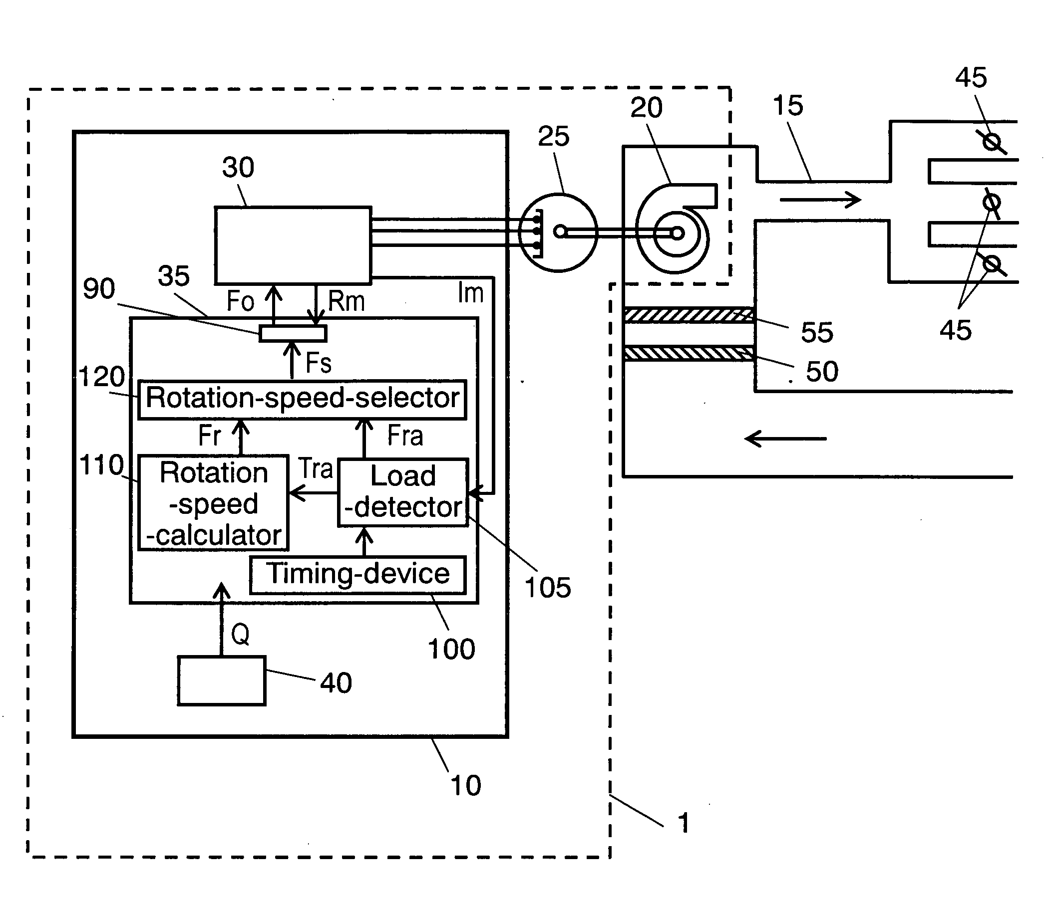
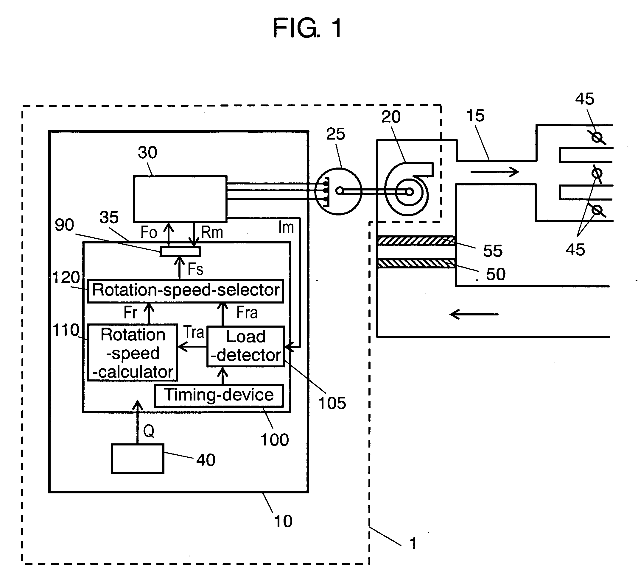
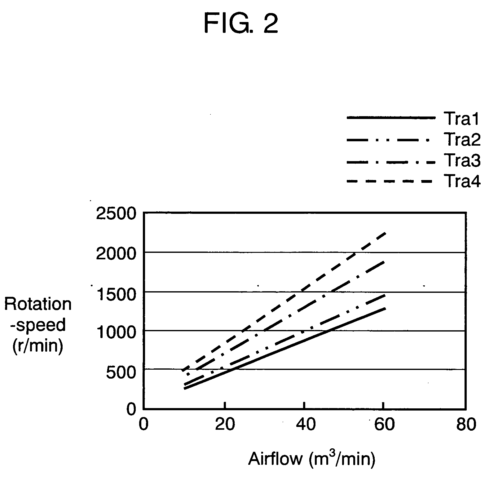
[0011] Generally, an amount of airflow is proportional to a rotation speed of a fan included in a duct when the duct condition is determined and the duct condition affects relative gradients or the like. If, therefore, the duct condition is detected somehow the relation between the amount of airflow and rotation speed can be determined. The duct condition is detectable as a load of the blower and the load of the blower is detectable as an output force of an electric motor as well. Moreover, because the output force of the electric motor is proportional to the product of the rotation speed and torque of the fan, the duct condition can be detected from the torque of the electric motor when the rotation speed is kept constant. In case of a DC motor, whose torque is proportional to the input current, the torque can be detected by measuring the motor input current. Therefore, the duct conditions can be detected by measuring the motor input current.

[0012] The present invention is to dete...


PUM


Abstract

The present invention provides an electric blower that performs: measuring an amount of airflow against a fan rotation speed of the blower with a load magnitude detected previously; determining an empirical formula to calculate a fan rotation speed to discharge an amount of target airflow in response to the magnitude of a load of the blower according to the data obtained from the above measurement repeated a plurality of times varying the magnitude of the load on the blower; operating, firstly in practice, the blower to detect the magnitude of the load of the blower, then to calculate the fan rotation speed to discharge the amount of target airflow using the empirical formula; and then changing the blower operation to the fan rotation speed given by the calculation.

Description

TECHNICAL FIELD [0001] The present invention relates to an electric blower for use in an air conditioner or the like coupled to a duct to supply an airflow necessary to a refrigerating cycle or the like in response to the duct condition. BACKGROUND ART [0002] There has been the kind of conventional electric blower that, observing always a fan rotation speed and the PWM (Pulse Width Modulation) signal for an electric motor to calculate the amount of airflow to compare the calculated amount of airflow with an amount of target airflow, corrects the control signal sent to the electric motor if there is a difference between the two, which is so-called a feedback control method. The technology is disclosed for instance in Japanese Patent Unexamined Publication No. H07-301450 (hereafter referred to as patent document 1). [0003]FIG. 3 shows a process flowchart of a conventional electric blower described in patent-document 1. As shown in FIG. 3, the control process of the conventional electr...

Claims


Application Information

Patent Timeline
IPC IPC(8): F04B49/00F04B17/00
CPCF04D27/004F24F11/0001F24F11/0079F24F2011/0073Y02B30/746F24F11/61F24F11/77Y02B30/70
Inventor OTAKI, SHIZUOFUJIWARA, SHINJIHARADA, KAZUHIRO
Owner PANASONIC CORP
Why Eureka
Try Eureka