Cleaning item

Active Publication Date: 2006-05-18
UNI CHARM CORP
View PDF15 Cites 45 Cited by
  • Summary
  • Abstract
  • Description
  • Claims
  • Application Information

AI Technical Summary

Benefits of technology

[0027] According to the manufacturing method of the cleaning item of the present invention, the main cleaning part comprises a brush part and an inserted part for the insertion of a gripper, each of which are manufactured separately. Additionally, these parts are joined by adhesive. Therefore, because it is unnecessary to linearly heat-seal the entire brush part and inserted part, the tolerance of the conditions of heat-sealing in the formation of the brush part and the inserted part is high. In addition, because the heat-sealing line of the brush part and the heat-sealing li

Problems solved by technology

However, the cleaning tool in Patent Document 1 is a cleaning tool which is used by fixing the handle, and the gripper cannot be attached or removed.
Therefore, it is unsuitable as a cleaning tool wherein th

Method used


Image

  • Cleaning item
  • Cleaning item
  • Cleaning item

Examples


Example

First Embodiment

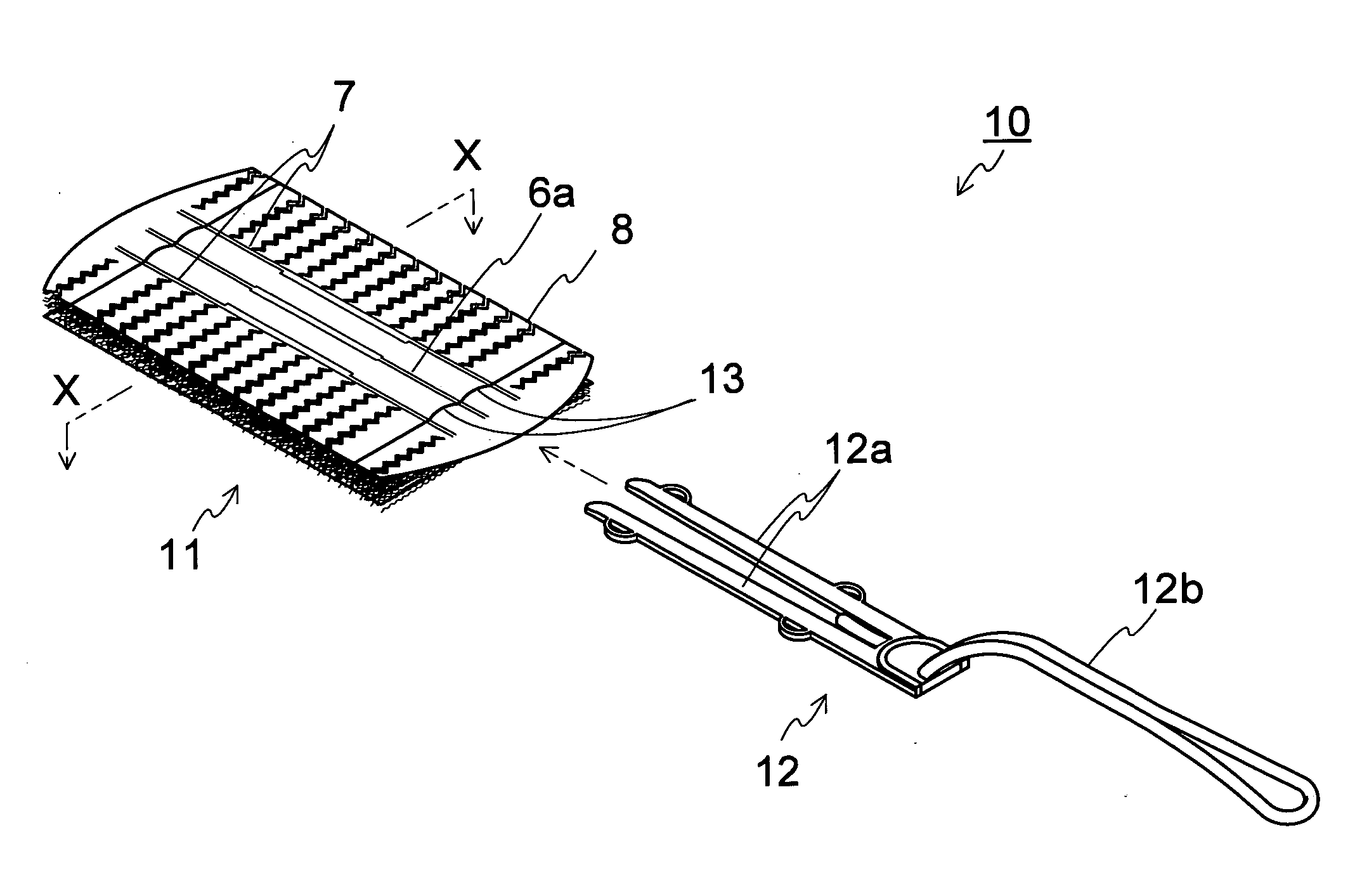
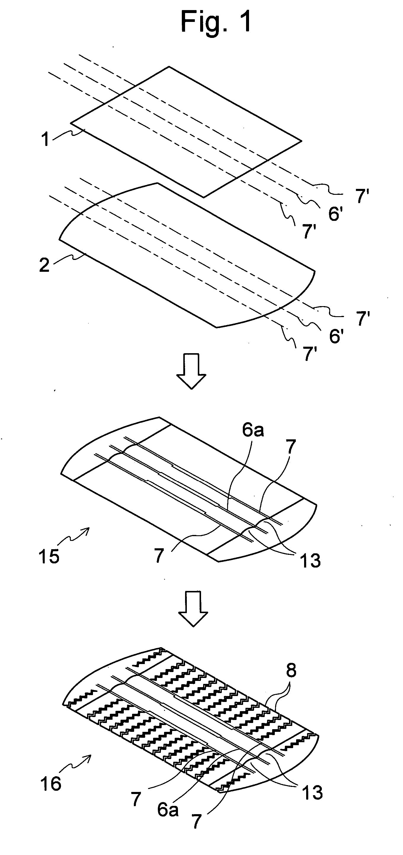
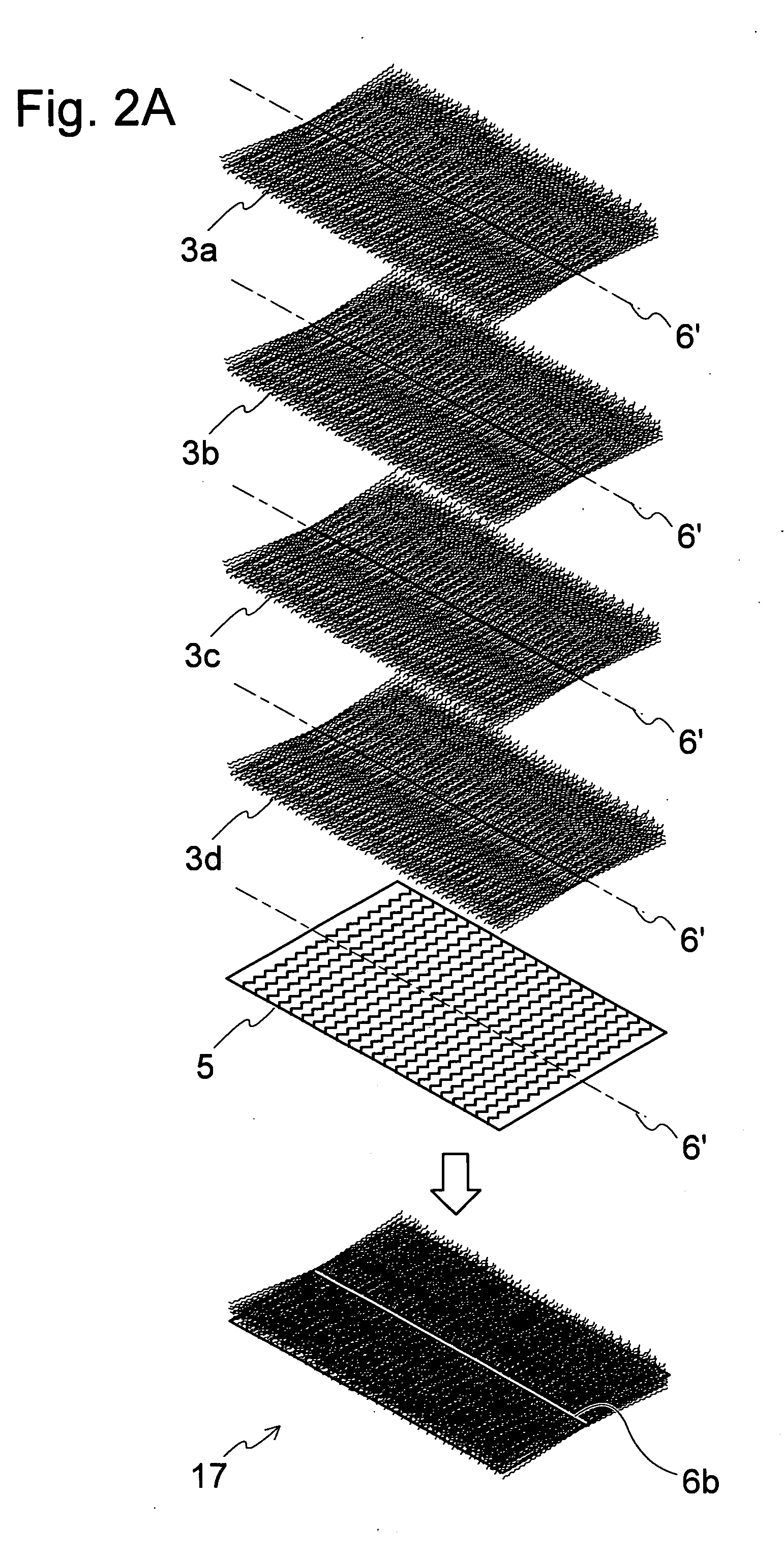
[0042] In FIG. 1 to FIG. 5, the first embodiment of a cleaning item and a manufacturing method thereof of the present invention are shown. FIG. 1 is a diagram showing the manufacturing process of the cleaning item and is an exploded perspective view of the inserted part formation process; FIG. 2A and FIG. 2B are diagrams showing the manufacturing process of the present invention and is an exploded perspective view of the brush part formation process; FIG. 3 is diagram showing the manufacturing process of the cleaning item and is an exploded perspective view of the joining process; FIG. 4 is a perspective view of the cleaning item; and FIGS. 5A and 5B are cross-sectional views in the X-X direction in FIG. 4. The first embodiment is explained below in line with the manufacturing process of the cleaning item.

[0043] First, as shown in FIG. 1, retention sheet 1 and base material sheet 2 are layered and heat-sealed on the two lines, joining line 7′ and the joining line 6...

Example

Second Embodiment

[0054] The manufacturing method of a cleaning item according to a second embodiment of the present invention is shown in FIG. 6 to FIG. 8. FIG. 6 is an exploded perspective diagram showing an inserted part formation process; FIG. 7 is an exploded perspective diagram showing a brush formation process; and FIG. 8 is an exploded perspective diagram showing a joining process.

[0055] According to this embodiment, the process differs from the first embodiment in that only inserted space 33 is formed in the inserted part formation process, strip part is not formed on the inserted part 36, and on the other hand, a strip sheet having a strip part is provided at the uppermost section of the brush part 37.

[0056] The cleaning item comprises a brush part wherein tow fiber bundle and strip sheet on which plural slits are formed from the outer boarder of a sheet formed from fibrous material are layered and the area in the vicinity of the center line of the layered body is integr...

Example

Third Embodiment

[0060] The manufacturing method of a cleaning item according to a third embodiment of the present invention is shown in FIG. 9 and FIG. 10. FIG. 9 is an exploded perspective view showing an inserted part formation process and FIG. 10 is an exploded perspective view showing a joining process.

[0061] This embodiment differs from the second embodiment in that, as shown in FIG. 9, in the inserted part formation process, an inserted part 46 which has one inserted space 43 is formed, and in the joining process, two inserted parts 46 are positioned roughly parallel on the brush part 37. The same brush as that in the second embodiment is used as brush part 37.

[0062] In the inserted part formation process, as shown in FIG. 9, an inserted part 46 with only one inserted space 43 is formed by layering retention sheet 41 and base material sheet 42 and heat-sealing only on two joining lines 7′.

[0063] Then, in the joining process, as shown in FIG. 10, the main cleaning part 45 i...


PUM


Abstract

The cleaning item of the present invention comprises: a brush part constructed from fibrous material; an inserted part with an inserted space into which a gripper is detachably inserted and which is formed by a pair of sheets, the inserted part being disposed in the brush part; and a joining member which joins the brush part and the inserted part.

Description

INCORPORATION BY REFERENCE [0001] Priority is claimed on Japanese Patent Application No. 2004-332496, filed Nov. 16, 2004, the content of which is incorporated herein by reference. FIELD OF THE INVENTION [0002] The present invention relates to a cleaning item for indoor-use having fibrous material, and more particularly, relates to a cleaning item used by attaching a brush part having fibrous material to a gripper. DESCRIPTION OF RELATED ART [0003] As disposable or replaceable conventional indoor cleaning items, there are items which have a brush part made from fibrous material such as, for example, tow fiber bundles or sheets cut into strips. [0004] As cleaning tool such as this, for example, a cleaning tool is disclosed in the Patent Document 1, US Patent Publication No. 898725, wherein a part of the sheets forming the brush is composed of felt or fiber and is used by fixing a handle to a predetermined position between the sheets. [0005] Furthermore, in the Patent Document 2, Japa...

Claims


Application Information

Patent Timeline
IPC IPC(8): A47L13/16A47L13/00
CPCA47L13/16A47L13/20A47L13/38A47L13/46B32B3/085B32B2432/00B32B5/06B32B5/26B32B7/12B32B2250/20B32B3/263A47L13/00
Inventor FUJIWARA, MASATOSHIONO, HIROKUNI
Owner UNI CHARM CORP
Why Eureka
Try Eureka