
Method for separating a multicomponent stream

a multi-component, fluid feed technology, applied in the direction of liquefaction, organic chemistry, lighting and heating apparatus, etc., can solve the problems of high energy cost associated with the separation of mixtures by distillation, substantial rise in energy cost, and general non-commercial use of distillation systems, so as to improve the operation of distillation systems, reduce the total heat duty, and reduce the effect of heat duty

Active Publication Date: 2006-05-18
EXXONMOBIL CHEM PAT INC
View PDF68 Cites 34 Cited by
  • Summary
  • Abstract
  • Description
  • Claims
  • Application Information

AI Technical Summary

Benefits of technology

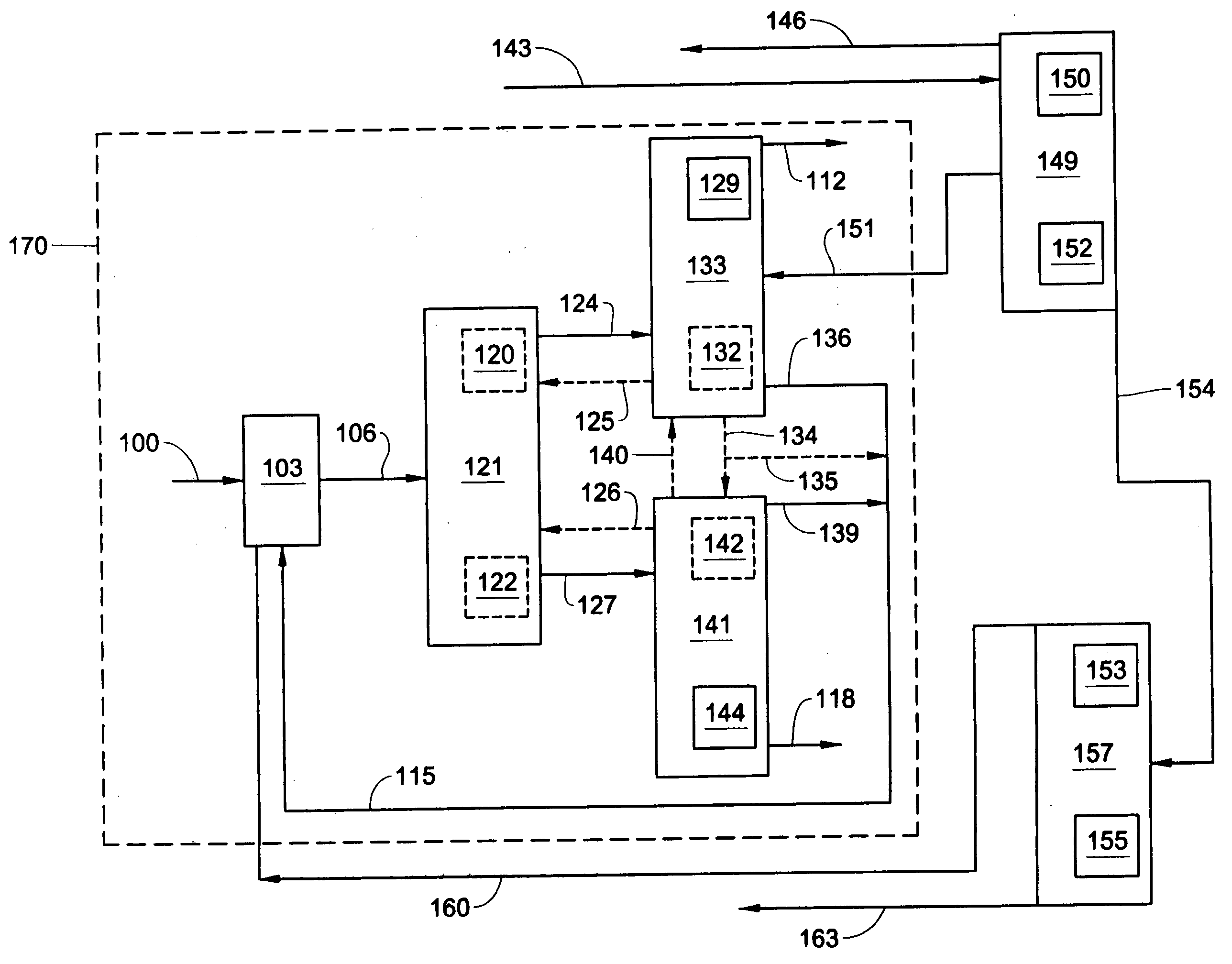
[0009] This invention relates to a method for improving the operation of a distillation system, said distillation system having a toluene disproportionation unit fluidically connected to a first distillation column, wherein said first distillation column comprises a first overhead product pipe and a bottoms mixture pipe, wherein said bottoms mixture pipe is fluidically connected to a second distillation column, wherein said second distillation column comprises a second overhead product pipe and a first bottoms product pipe, said method including the steps of: reducing the heat duty on the first distillation column; fluidically connecting the first overhead product pipe to the second distillation column; increasing the heat duty on the second distillation column; and providing a first middle product pipe fluidically connected to the second distillation column; wherein the heat duty on the first distillation column and the heat duty on the second distillation column are changed in a manner that reduces the total heat duty by at least about 15 percent.

Problems solved by technology

A significant problem in the chemical and petroleum industry is the high energy costs associated with the separation of mixtures by distillation, and in particular with the separation of fluid streams having three or more components.
This has become especially true in recent years with the substantial rise in energy costs.
Some fully thermally coupled distillation systems provide some energy cost savings; however, due to control difficulties these distillation systems have generally not been commercially used.

Method used


Image

  • Method for separating a multicomponent stream
  • Method for separating a multicomponent stream
  • Method for separating a multicomponent stream

Examples


examples

[0046] The Comparative Example, Example 1, and Example 2 are simulations conducted in the distillation design software Simulation Science Pro / II, by Invensys plc. The following assumptions and requirements were selected in the software: a Peng-Robinson thermodynamic method, the column overhead pressure was 156.5 kPa, the columns had a pressure drop of 1.04 kPa per theoretical stage, the change in pressure on the reboiler was equal to the change in pressure per theoretical stage, the condenser pressure on all columns was 135.8 kPa, and the condenser was assumed to run at the bubble point. The aggregate number of theoretical stages in Example 1 is the same as the aggregate number of theoretical stages in the Comparative Example. The aggregate number of theoretical stages in Example 2 is less than the aggregate number of theoretical stages in the Comparative Example. The divided wall column was simulated using two separate columns. One column represented the overall divided wall column...

example 1

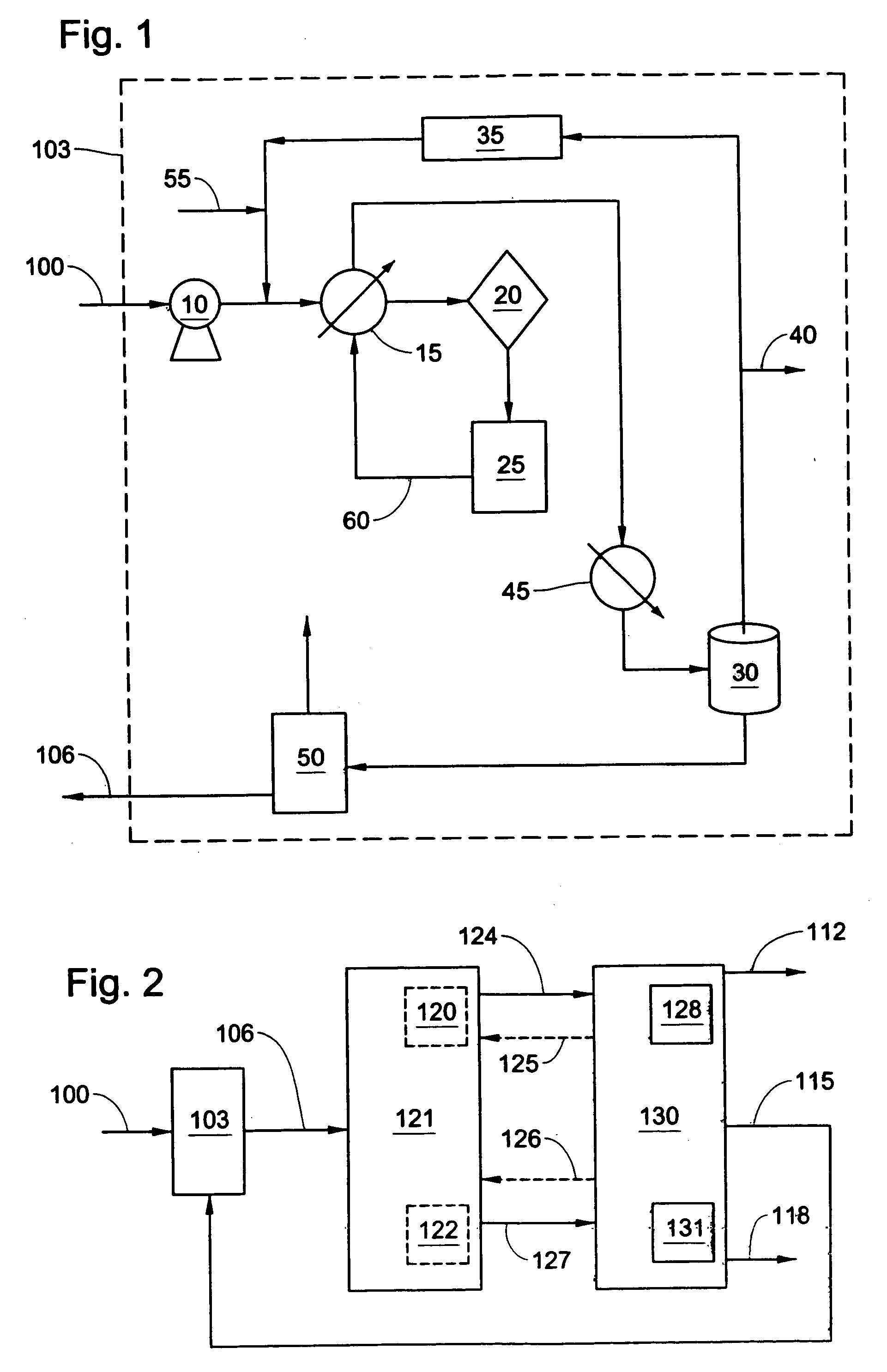
[0054] In the first example the fractionation distillation system was applied downstream of a toluene disproportionation unit. The first example can best be understood by an examination of FIGS. 2 and / or 7. However, FIGS. 2 and 7 were not drawn to specifically embody the first example. In the first example, a fluid stream comprising three major components; benzene, toluene, and alkyl benzene, was fed into a toluene disproportionation unit. Within the toluene disproportionation unit the effluent of the toluene disproportionation reactor was modified such that the effluent contained about 15.2 mole percent benzene, 70.4 mole percent toluene, 13.8 mole percent alkyl benzene, the balance mole percent was byproducts, the temperature was 140.6° C., and the pressure was 790.8 kPa. The effluent of the toluene disproportionation unit was then fed into a first distillation column. The heat duty on the reboiler of the first distillation column was about 27,823 kJ / (kg mole product). The first d...

example 2

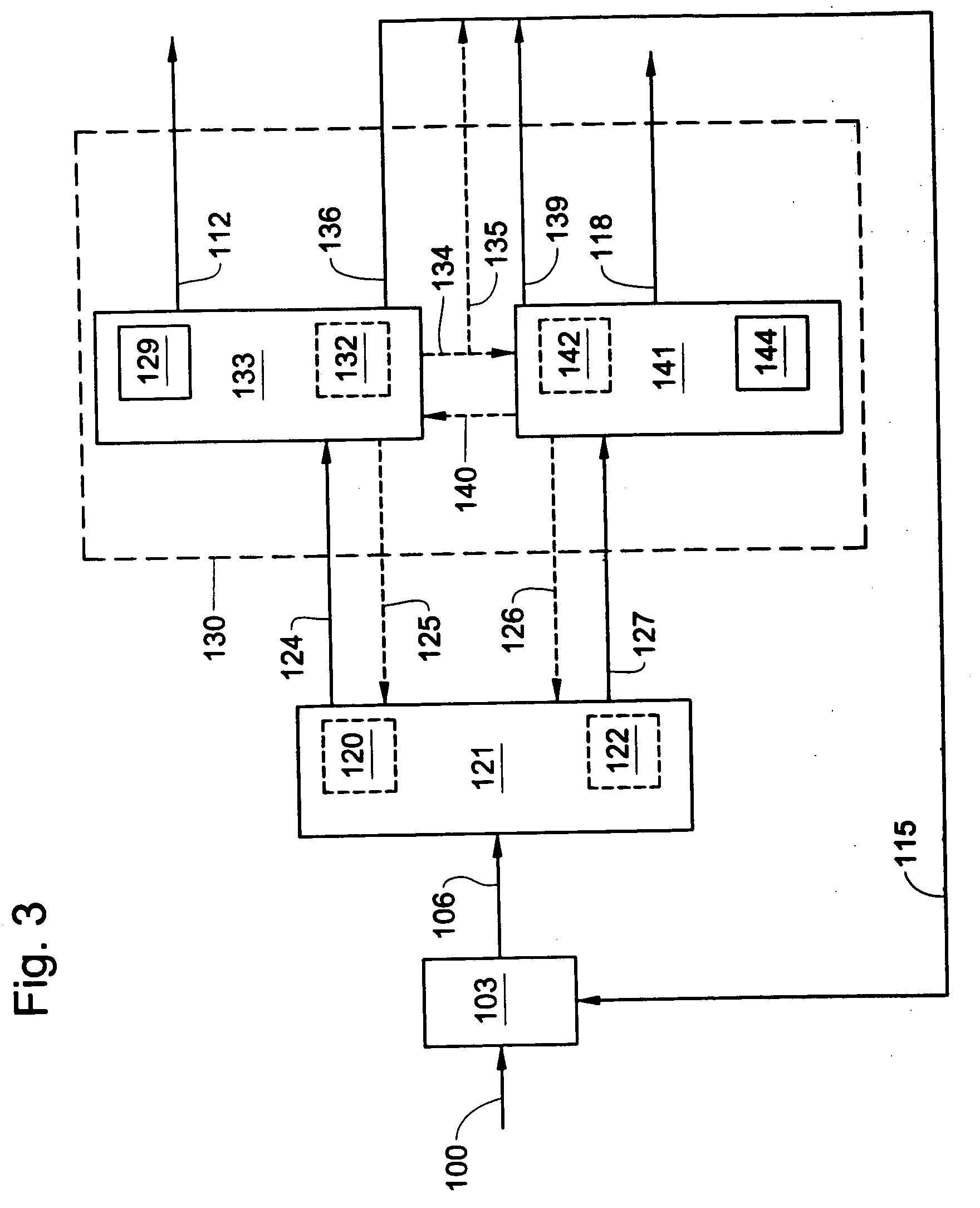
[0056] The second example can best be understood by an examination of FIG. 5. However, FIG. 5 was not drawn to specifically embody the second example. In the second example the fractionation distillation system, a divided wall column, was applied downstream of a toluene disproportionation unit. In this example the vertical partition was placed along a cross section of the divided wall column such that the internal vapor flow into the feed side of the divided wall was 42.8% of the total vapor flow and the internal liquid flow into the feed side of the divided wall was 28.3% of the total liquid flow. A fluid stream comprising three major components; benzene, toluene, and alkyl benzene, was fed into a toluene disproportionation unit. Within the toluene disproportionation unit the effluent of the toluene disproportionation reactor was modified such that the effluent contained about 15.2 mole percent benzene, 70.4 mole percent toluene, 13.8 mole percent alkyl benzene, the balance mole pe...


PUM

PropertyMeasurementUnit
pressureaaaaaaaaaa
pressureaaaaaaaaaa
temperatureaaaaaaaaaa

Abstract

This invention relates to a method for separating a stream having benzene, toluene and alkyl benzene, said method comprising: feeding the stream into a first distillation column, wherein the stream comprises between about 60 mole percent to about 85 mole percent toluene, between about seven mole percent to about 20 mole percent benzene, and between about seven mole percent to about 20 mole percent alkyl benzene; separating the steam into a first mixture stream and a second mixture stream; feeding the first mixture stream and the second mixture stream into a distillation system; separating the first mixture stream and the second mixture stream into a first product stream, a system recycle stream, and a second product stream.

Description

FIELD OF THE INVENTION [0001] This invention relates generally to energy-efficient distillation systems for the separation of a multicomponent fluid feed. More particularly, this invention relates to separation systems for the separation of fluid mixtures having benzene, toluene, and alkyl benzene. BACKGROUND OF THE INVENTION [0002] A significant problem in the chemical and petroleum industry is the high energy costs associated with the separation of mixtures by distillation, and in particular with the separation of fluid streams having three or more components. This has become especially true in recent years with the substantial rise in energy costs. As a result, there is a need to develop distillation systems that provide for adequate separation of the components, at a lower energy cost. Some fully thermally coupled distillation systems provide some energy cost savings; however, due to control difficulties these distillation systems have generally not been commercially used. Thus ...

Claims


Application Information

Patent Timeline
Patent Type & Authority Applications(United States)
IPC IPC(8): F25J3/00
CPCC07C7/04C07C15/02Y02P20/10
Inventor PORTER, JOHN ROGER
Owner EXXONMOBIL CHEM PAT INC
Learn More