Fuel supply system for marine structure having reliquefaction apparatus and high-pressure natural gas injection engine

a technology of reliquefaction apparatus and fuel supply system, which is applied in the direction of machines/engines, lighting and heating apparatus, and container discharging methods, etc., can solve the problems of low liquefaction efficiency, flash gas may be generated, and low reliquefaction efficiency, so as to reduce the load, efficiently supply, and minimize the energy consumption of the reliquefaction apparatus

Inactive Publication Date: 2014-03-06
DAEWOO SHIPBUILDING & MARINE ENG CO LTD
View PDF11 Cites 17 Cited by
  • Summary
  • Abstract
  • Description
  • Claims
  • Application Information

AI Technical Summary

Benefits of technology

[0035]The present invention may provide a fuel supply system for a high-pressure natural gas injection engine. Specifically, BOG generated in a liquefied gas storage tank is used as fuel for a high-pressure natural gas injection engine (e.g., an ME-GI engine). The BOG is compressed to a medium pressure higher than a conventional pressure, reliquefied, and then supplied to the high-pressure natural gas injection engine. A recondenser is installed, and a portion of the generated BOG is recondensed by the recondenser to reduce a load on an reliquefaction apparatus.
[0036]According to the fuel supply system for the high-pressure natural gas injection engine according to the present invention, fuel can be efficiently supplied to the high-pressure natural gas injection engine, and the energy consumption of the reliquefaction apparatus can be minimized.
[0037]As opposed to the related art in which the BOG is compressed to a low pressure of about 4 to 8 bara, the fuel supply system for the high-pressure natural gas injection engine according to the present invention compresses the BOG to a medium pressure of about 12 to 45 bara and then reliquefied. As the pressure of the BOG increases, the liquefaction energy decreases. Therefore, the liquefaction energy consumed in reliquefaction may be reduced.
[0038]Also, in the fuel supply system for the high-pressure natural gas injection engine according to the present invention, since the pressure of the BOG in the BOG reliquefaction is a medium pressure higher than that of the related art, the liquefying point of the BOG increases. Therefore, thermal stress applied to a heat exchanger for reliquefaction is reduced, and a heat duty of a high-pressure gasifier is reduced, leading to a reduction in the size of the apparatus.
[0039]Also, since the liquefied BOG compressed to a medium pressure is compressed to a high pressure, power of a high-pressure pump is reduced.
[0040]Also, in the fuel supply system for the high-pressure natural gas injection engine according to the present invention, a nonflammable mixed refrigerant is used as a refrigerant of a reliquefaction apparatus for the BOG reliquefaction. Therefore, the fuel supply method according to the present invention is more efficient than a conventional nitrogen refrigeration cycle, and can reliquefy the BOG more safely than a conventional mixed refrigerant cycle.

Problems solved by technology

The generated natural gas may increase the internal pressure of the storage tank and accelerate the flow of the natural gas due to the rocking of the vessel, causing structural problems.
However, the LNG stored in the storage tank is maintained at an ambient pressure state, and therefore, if a pressure of the liquefied BOG is excessively high, flash gas may be generated when the BOG is returned to the storage tank.
Consequently, the BOG needs to be compressed to the above-mentioned low pressure of about 4 to 8 bara, in spite of low reliquefaction efficiency.
Also, it is well known in the art that it is technically inappropriate to compress BOG to a pressure higher than the above-mentioned pressure.
Meanwhile, since the nitrogen refrigeration cycle uses nitrogen gas (N2) as a refrigerant, the liquefaction efficiency is low.
Also, the mixed refrigerant cycle uses a refrigerant mixed with nitrogen and hydrocarbon gases as a refrigerant, the stability is low.
The nitrogen reverse Brayton cycle used for the offshore LNG liquefaction apparatus is relatively simple in the configuration of the apparatus and thus is advantageous to a limited vessel or offshore plant, but has low efficiency.
The mixed-refrigerant Joule-Thomson refrigeration cycle used for the onshore LNG liquefaction plant has relatively high efficiency but is complicated in the configuration of the apparatus because a separator needs to be used for separating a mixed refrigerant when a gaseous state and a liquid state coexist due to the feature of the mixed refrigerant.

Method used


Image

  • Fuel supply system for marine structure having reliquefaction apparatus and high-pressure natural gas injection engine
  • Fuel supply system for marine structure having reliquefaction apparatus and high-pressure natural gas injection engine
  • Fuel supply system for marine structure having reliquefaction apparatus and high-pressure natural gas injection engine

Examples


first embodiment

Modified Example of First Embodiment

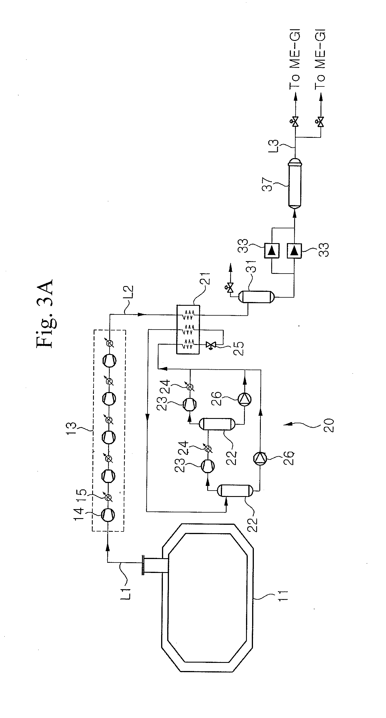
[0090]FIG. 3B illustrates a fuel supply system according to a modified example of the first embodiment of the present invention. Since the modified example of the first embodiment is partially different from the first embodiment in terms of the configurations of a BOG compression unit 13 and a liquefaction apparatus 20, only the difference therebetween will be described below.

[0091]The modified example of the first embodiment illustrated in FIG. 3B is substantially identical to the first embodiment illustrated in FIG. 3A in that the BOG compressing unit 13 includes five BOG compressors 14, but is different from the first embodiment in that an intermediate cooler 15 is not disposed between the first and second BOG compressors and between the second and third BOG compressors included in the BOG compression unit 13. According to the present invention, the intermediate cooler 15 may or may not be disposed between every two BOG compressors 14.

[0092]Als...

second embodiment

Modified Example of Second Embodiment

[0117]FIG. 7B is a configuration diagram illustrating a fuel supply system according to a modified example of the second embodiment of the present invention. As described in the modified example of the first embodiment, the modified example of the second embodiment is partially different from the second embodiment in terms of the configurations of a BOG compression unit 13 and a reliquefaction apparatus 20.

[0118]That is, the modified example of the second embodiment is substantially identical to the second embodiment in that the BOG compression unit 13 includes five BOG compressors 14, but is different from the second embodiment in that an intermediate cooler 15 is not disposed between the first and second BOG compressors and between the second and third BOG compressors included in the BOG compression unit 13. According to the present invention, the intermediate cooler 15 may or may not be disposed between every two BOG compressors 14.

[0119]Like ...

third embodiment

Modified Example of Third Embodiment

[0125]FIG. 8B is a configuration diagram illustrating a fuel supply system according to a modified example of the third embodiment of the present invention. The modified example of the third embodiment is partially different from the third embodiment in terms of the configuration of a reliquefaction apparatus 20.

[0126]That is, like the reliquefaction apparatus 20 according to the modified example of the first embodiment illustrated in FIG. 3B, the reliquefaction apparatus 20 according to the modified example of the third embodiment includes a cold box 21 configured to exchange heat between a refrigerant and BOG, a compression unit configured to compress the refrigerant that is heated and at least partially gasified by the cold box 21, an expansion unit configured to expand the compressed refrigerant to reduce the temperature thereof, and a gas-liquid refrigerant separator configured to separate the gaseous refrigerant and the liquid refrigerant.

[0...


PUM


Abstract

Provided is a fuel supply system for a marine structure. The fuel supply system includes a BOG compression unit configured to receive and compress BOG generated in a storage tank, a reliquefaction apparatus configured to receive and liquefy the BOG compressed by the BOG compression unit, a high-pressure pump configured to compress the liquefied BOG generated by the reliquefaction apparatus, and a high-pressure gasifier configured to gasify the liquefied BOG compressed by the high-pressure pump. The fuel supply system includes a recondenser installed at an upstream side of the high-pressure pump and configured to recondense a portion or all of the generated BOG by using liquefied gas received from the storage tank. The BOG compression unit compresses BOG to a pressure of about 12 to 45 bara such that the BOG is liquefied under the compression pressure of the BOG compression unit.

Description

TECHNICAL FIELD[0001]The present invention relates to a fuel supply system for a high-pressure natural gas injection engine, and more particularly, to a fuel supply system for a marine structure such as a liquefied natural gas (LNG) carrier having a boil-off gas (BOG) reliquefaction apparatus and a high-pressure natural gas injection engine (e.g., a MAN Electronic-Gas Injection (ME-GI) engine), which can efficiently supply fuel to the high-pressure natural gas injection engine and minimize energy consumption in the BOG reliquefaction apparatus.BACKGROUND ART[0002]Recently, the consumption of natural gas, such as liquefied natural gas (LNG) or liquefied petroleum gas (LPG), has been rapidly increasing throughout the world. Liquefied gas is transported in a gaseous state through onshore or offshore gas pipelines, or transported to a remote consumption place while being stored in a liquefied state inside a liquefied gas carrier. Liquefied gas, such as LNG or LPG, is obtained by cooling...

Claims


Application Information

Patent Timeline
Patent Type & Authority Applications(United States)
IPC IPC(8): F25J1/00
CPCF25J1/0025F02M21/0227F02M21/0245F02M21/0287F25J1/0052F25J1/0097F25J1/0212F25J1/023F25J1/0254F25J1/0277F25J1/0278F25J1/0291F25J2220/62F25J2230/08F25J2230/30F25J2230/60F25J2235/60F25J2290/62F17C13/004F17C2201/052F17C2221/033F17C2223/0161F17C2265/034F17C2265/037F17C2265/066F17C2270/0105F17C2270/0113F25J1/0045F25J2205/30Y02T10/30F25J2215/02F25J2205/90F17C5/04
Inventor JUNG, SEUNG KYOJUNG, JE HEONLEE, JUNG HANLEE, SUNG JUNSHIN, HYUN JUNCHOI, DONG KYU
Owner DAEWOO SHIPBUILDING & MARINE ENG CO LTD
Why Eureka
Try Eureka