Method, control appliance, and computer program for detecting defective pressure sensors in an internal combustion engine

a technology of pressure sensor and internal combustion engine, which is applied in the direction of electric control, machines/engines, instruments, etc., can solve the problems of defective pressure sensor of intake-manifold and/or exhaust-gas recirculation valve, defective exhaust-gas recirculation valve, and load of internal combustion engine no longer controlled via throttl

Inactive Publication Date: 2006-05-18
ROBERT BOSCH GMBH
View PDF4 Cites 16 Cited by
  • Summary
  • Abstract
  • Description
  • Claims
  • Application Information

AI Technical Summary

Problems solved by technology

Thus, e.g., in a first part of the method, it can initially be deduced that, when a particular deviation is present, either the intake-manifold pressure sensor and / or the exhaust-gas recirculation valve is defective.
If the intake-manifold pressure is the same in both cases, it may be deduced that there is a defect in the intake-manifold pressure sensor; however, if the pressure in the intake manifold while the engine is stopped is less than that when the engine is being operated, it may then be deduced that an exhaust-gas recirculation valve is defective.
However, in internal combustion engines having variable valve timing, i.e., in internal combustion engines having throttleless load control, the load of the internal combustion engine is no longer controlled via the throttle valve and, therefore, via the pressure in the intake manifold, but rather via a change in its valve timing and / or its valve lift.
However, as explained above, since the load control in internal combustion engines having fully variable valve timing is no longer implemented via the throttle valve, all of the already known diagnostic methods for pressure sensors, which are based on deriving a load signal representing the load of the internal combustion engine from the angular position of the throttle valve or the pressure in the intake manifold, are no longer applicable to internal combustion engines having fully variable valve timing.

Method used


Image

  • Method, control appliance, and computer program for detecting defective pressure sensors in an internal combustion engine
  • Method, control appliance, and computer program for detecting defective pressure sensors in an internal combustion engine
  • Method, control appliance, and computer program for detecting defective pressure sensors in an internal combustion engine

Examples


Embodiment Construction

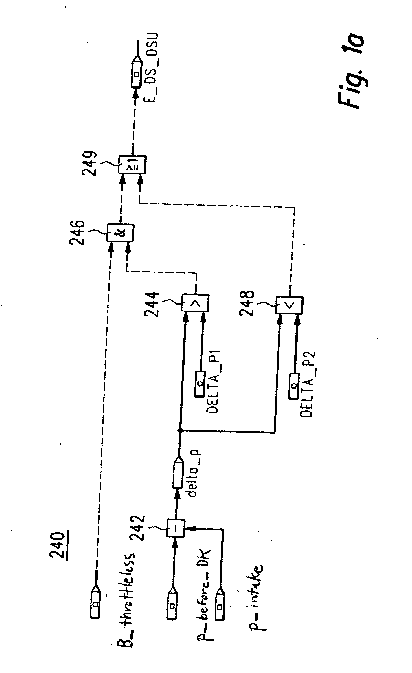
[0019]FIG. 1a illustrates a method for determining whether or not at least one of two pressure sensors, namely the intake-manifold pressure sensor and / or the ambient-pressure sensor, is defective in the case of an internal combustion engine having variable valve timing as shown in FIG. 3. The method steps illustrates FIG. 1a do not allow one to specifically determine which of the two pressure sensors is defective; such a determination may be made with the aid of further steps of the method described below with reference to FIG. 2.

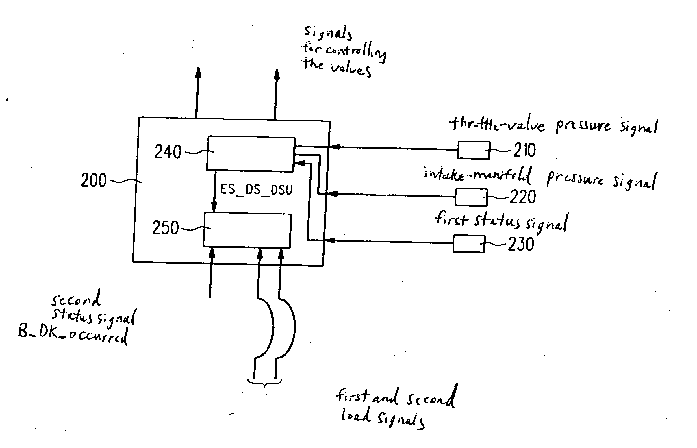
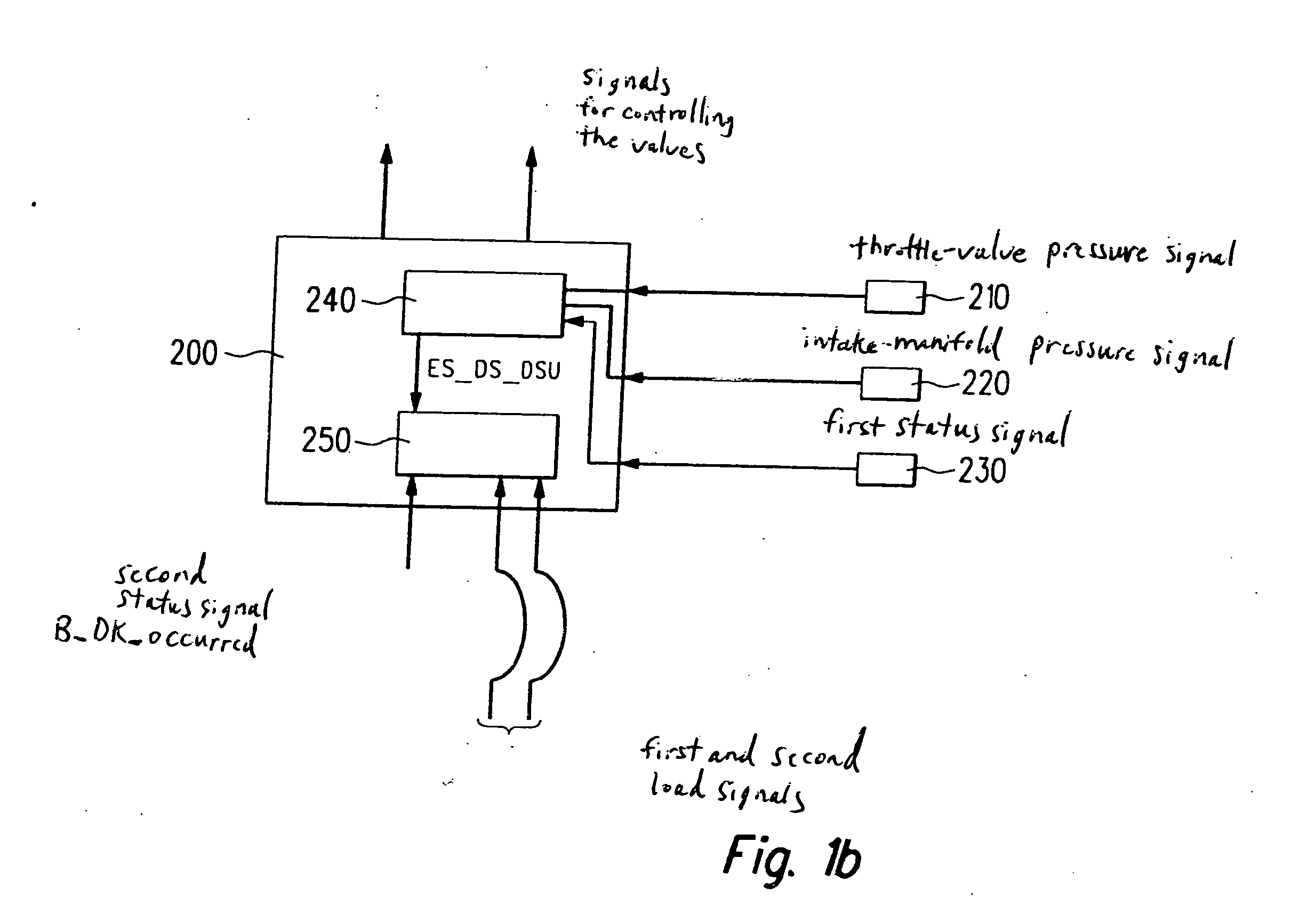
[0020] The method is illustrated in FIG. 1a by showing the functional layout of a first logic module 240 according to the present invention, which may be a component of a control unit 200 for controlling the valves of internal combustion engine 100, which control unit 200 is shown in FIG. 1b. First logic module 240 allows the claimed method to be implemented. The layout of first logic module 240 is described below in detail; the individual steps of the cla...


PUM


Abstract

A method, a control unit, and a computer program for detecting a defective intake-manifold pressure sensor and / or a defective ambient-pressure sensor in an internal combustion engine having a variable valve timing are provided. The desired detection is carried out exclusively on the basis of a direct evaluation of the pressure upstream from the throttle valve and the pressure in the intake manifold. This method eliminates the need for deriving load signals from these pressures, at least for the determination as to whether at least one of the pressure sensors is defective.

Description

FIELD OF THE INVENTION [0001] The present invention relates to a method, a control unit, and a computer program for detecting a defective intake-manifold pressure sensor and / or a defective ambient-pressure sensor in an internal combustion engine. BACKGROUND INFORMATION [0002] An intake-manifold pressure sensor is used, for example, to diagnose the exhaust-gas recirculation in an internal combustion engine and therefore supplies important information for a control unit to control the internal combustion engine. A load signal representing the current load of the internal combustion engine, or the setting of a correct torque selected by the driver, may be derived from the pressure in the intake manifold. In addition, an optimum injection time in an internal combustion engine having throttle control may be ascertained from the load signal. [0003] Because of the high importance of the intake-manifold pressure sensor during the operation of an internal combustion engine, it is desirable f...

Claims


Application Information

Patent Timeline
Patent Type & Authority Applications(United States)
IPC IPC(8): G01M19/00F01L1/34G01M99/00F02D41/22
CPCF02D41/222F02D2041/001F02D2200/0406F02D2200/703Y02T10/40
Inventor MONINGER, THOMAS
Owner ROBERT BOSCH GMBH
Why Eureka
Try Eureka