Foldable campfire extinguisher

a campfire and fire extinguisher technology, applied in the field of fire extinguishing devices, can solve the problems of embers, coals and other ignited materials still burning, and achieve the effect of reducing the risk of fir

Inactive Publication Date: 2006-05-18
SMOLINSKY JERRY
View PDF27 Cites 9 Cited by
  • Summary
  • Abstract
  • Description
  • Claims
  • Application Information

AI Technical Summary

Benefits of technology

[0009] Each of the respective pie-shaped plates includes an apex through which a locking device is placed not only operating as a pivot for deployment of the respective plates but also, when tightened, provides a means for holding the fully deployed plates in their operable position. Preferably, the locking device is of a bolt and screw type that may be readily hand-operated for convenience and ease of deployment of the plates. Also, each of the respective pie-shaped plates may include apertures which when registered with apertures of adjacent plates provide a passageway for insertion of a pin that may be employed for maintaining the plurality of plates in either of their deployed positions. In essence, the firebed extinguisher is in a dome configuration in its fully deployed position, and the diameter of the dome at its terminating edges is large enough to surround the firebed so that the dome-shaped firebed extinguisher acts as a barrier to prevent oxygen from reaching the combustible materials or coals of the firebed.
[0010] Therefore, it is among the primary objects of the present invention to provide a novel firebed extinguisher that may have two positions with one position being fully deployed to a dome-shaped device that may be placed over a firebed and a second position where a compact arrangement of the device is provided for transport and easy carrying and storage.
[0012] Yet another object of the invention is to provide a firebed extinguisher which completely surrounds and covers the firebed so as to prevent oxygen from reaching combustible materials within the extinguisher.

Problems solved by technology

Problems and difficulties have been encountered when extinguishing the fire in a firebed which stem largely from the fact that the combustible material is not starved of oxygen so that even if flames have been extinguished, embers, coals and other ignited materials may still flame after a time delay.

Method used


Image

  • Foldable campfire extinguisher
  • Foldable campfire extinguisher
  • Foldable campfire extinguisher

Examples


Embodiment Construction

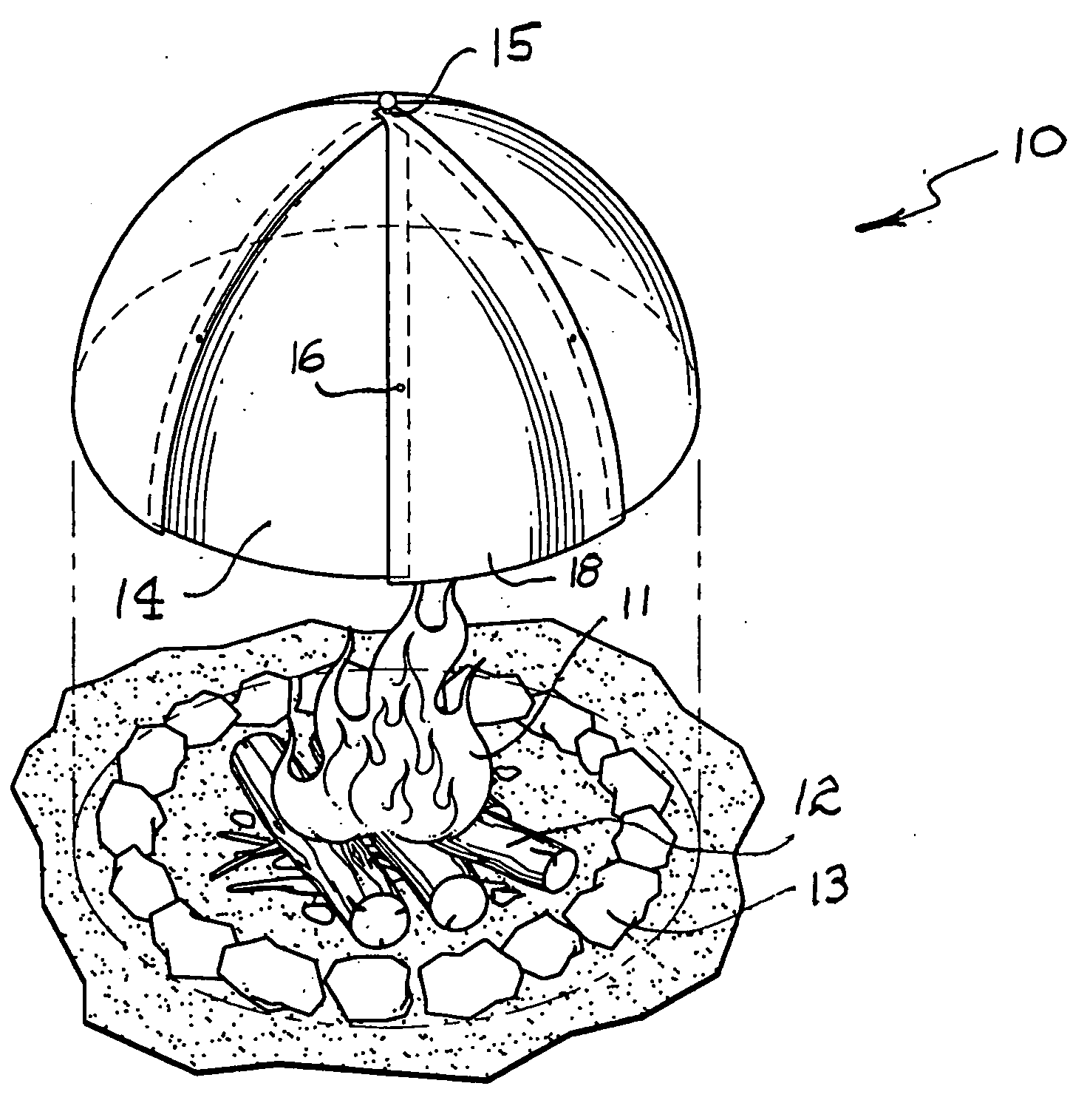
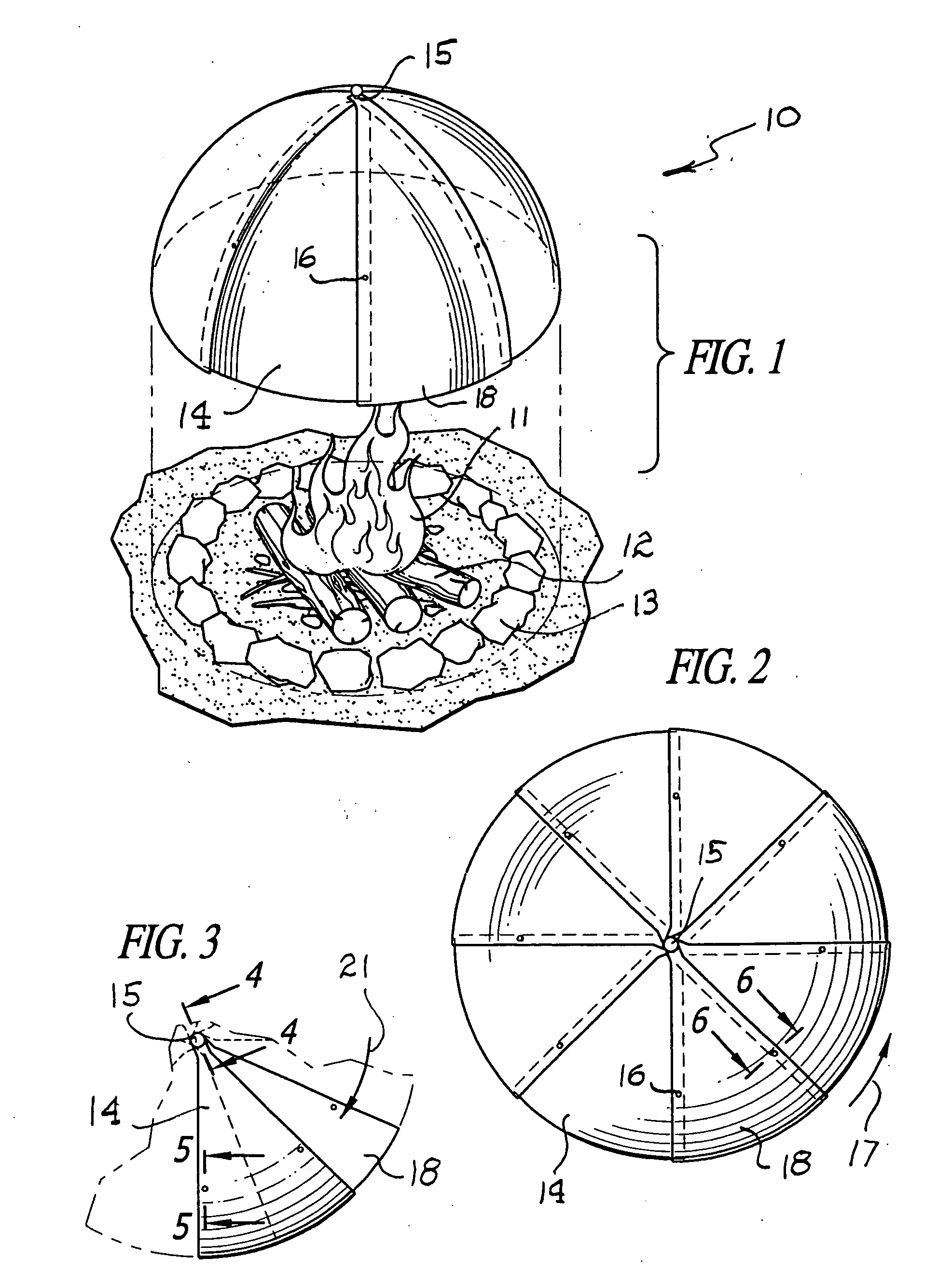
[0022] Referring to FIG. 1, the firebed extinguisher incorporating the present invention is illustrated in the general direction of arrow 10 which illustrates a firebed at a camp site having flames 11 generated from a source of combustible material, such as wood 12. The firebed is surrounded by a plurality of rocks 13 which serve to maintain heat in the center of the firebed.

[0023] In order to extinguish the flames 11 and to remove oxygen from any coals remaining in the firebed, the firebed extinguisher 10 is lowered over the complete firebed area including the combustible material 12, the heated rocks 13 and the flames 11.

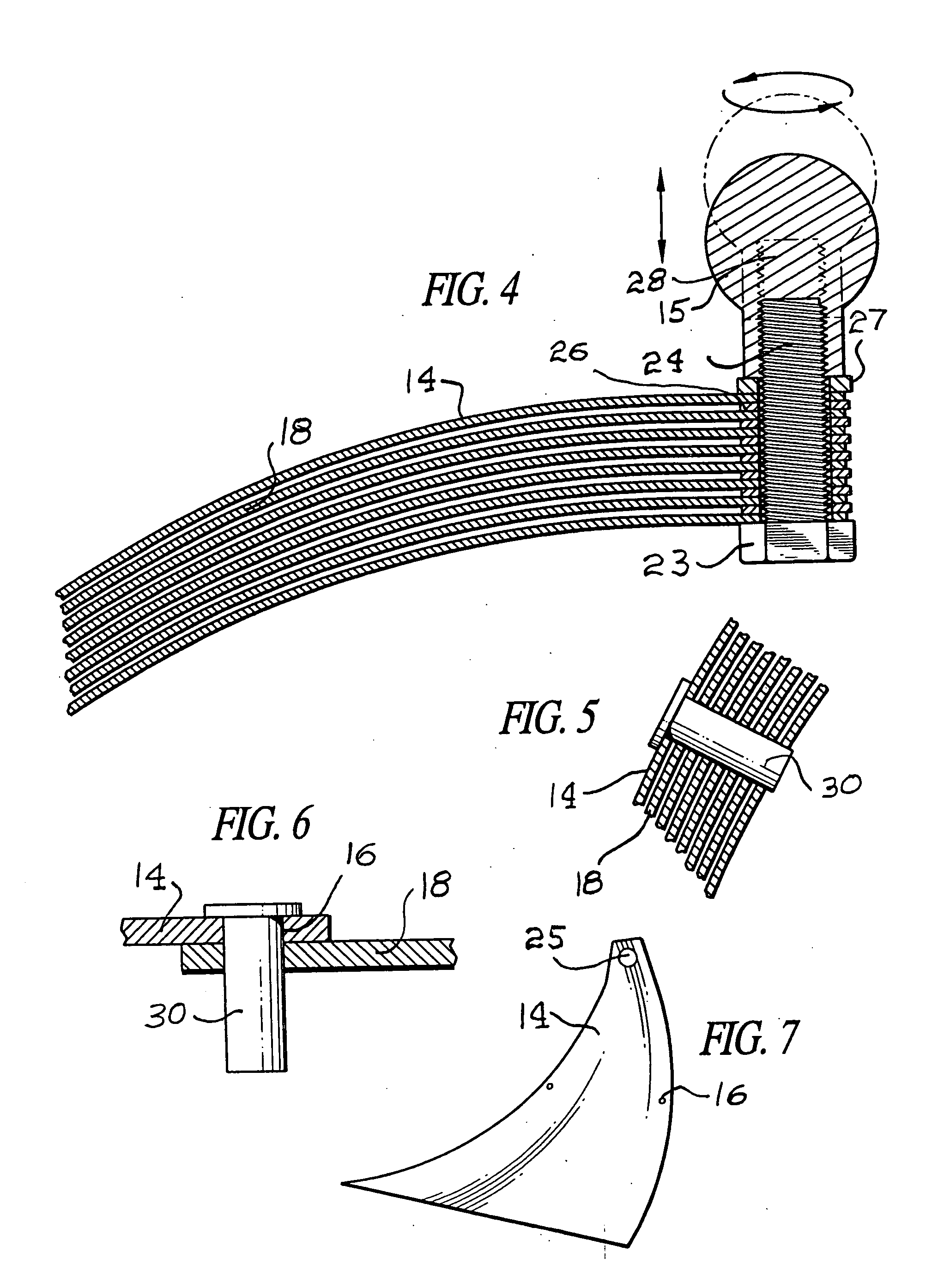
[0024] It can be seen that the firebed extinguisher includes a plurality of pie-slice-like or triangular-like shaped plates or panels, such as panel 14. Preferably, the panels are made of metal. The panels which are held together by a screw-type fastening means 15. The extinguisher 10 is illustrated in its fully deployed condition so that the edge marginal regio...


PUM


Abstract

A novel method for camping with the extinguishment of a campfire comprised of the steps of providing a collapsible campfire extinguisher in compact configuration; traveling to a camp site; utilizing a campfire; deploying the camp fire extinguisher in operable position and placing it over the campfire. A collapsible camp fire extinguisher device comprised of a plurality of panels having registerable holes and a locking means whereby the device transforms from a compact storage position to fanned-out dome position and is operative to extinguish a campfire by starvation of oxygen.

Description

CROSS REFERENCE TO RELATED APPLICATIONS [0001] We hereby claim the benefit of my earlier filed provisional application (application No. 60 / 627,323) filed Nov. 12, 2004.BACKGROUND OF THE INVENTION [0002] 1. Field of the Invention [0003] The present invention relates to the field of fire extinguishing devices, and more particularly to a novel firebed extinguisher device deployable from a compact storage position into a dome-shaped shell that may be placed as a unitary device over a firebed in order to rob the firebed of oxygen so that any flame, coals, or combustible materials will be extinguished. [0004] 2. Brief Description of the Prior Art [0005] In the past, it has been the conventional practice to build a fire for cooking purposes using a firebed composed of combustible materials and, particularly while camping, a ring of rocks are placed around the firebed. In other instances, holes are dug and lined with rocks so as to provide a firebed, while in other instances, a steel bowl, ...

Claims


Application Information

Patent Timeline
Patent Type & Authority Applications(United States)
IPC IPC(8): F24B1/18
CPCA47J33/00F23Q25/00
Inventor SMOLINSKY, JERRY
Owner SMOLINSKY JERRY
Why Eureka
Try Eureka