[0010] This object is achieved according to the invention for sealing elements of the aforementioned type in that the
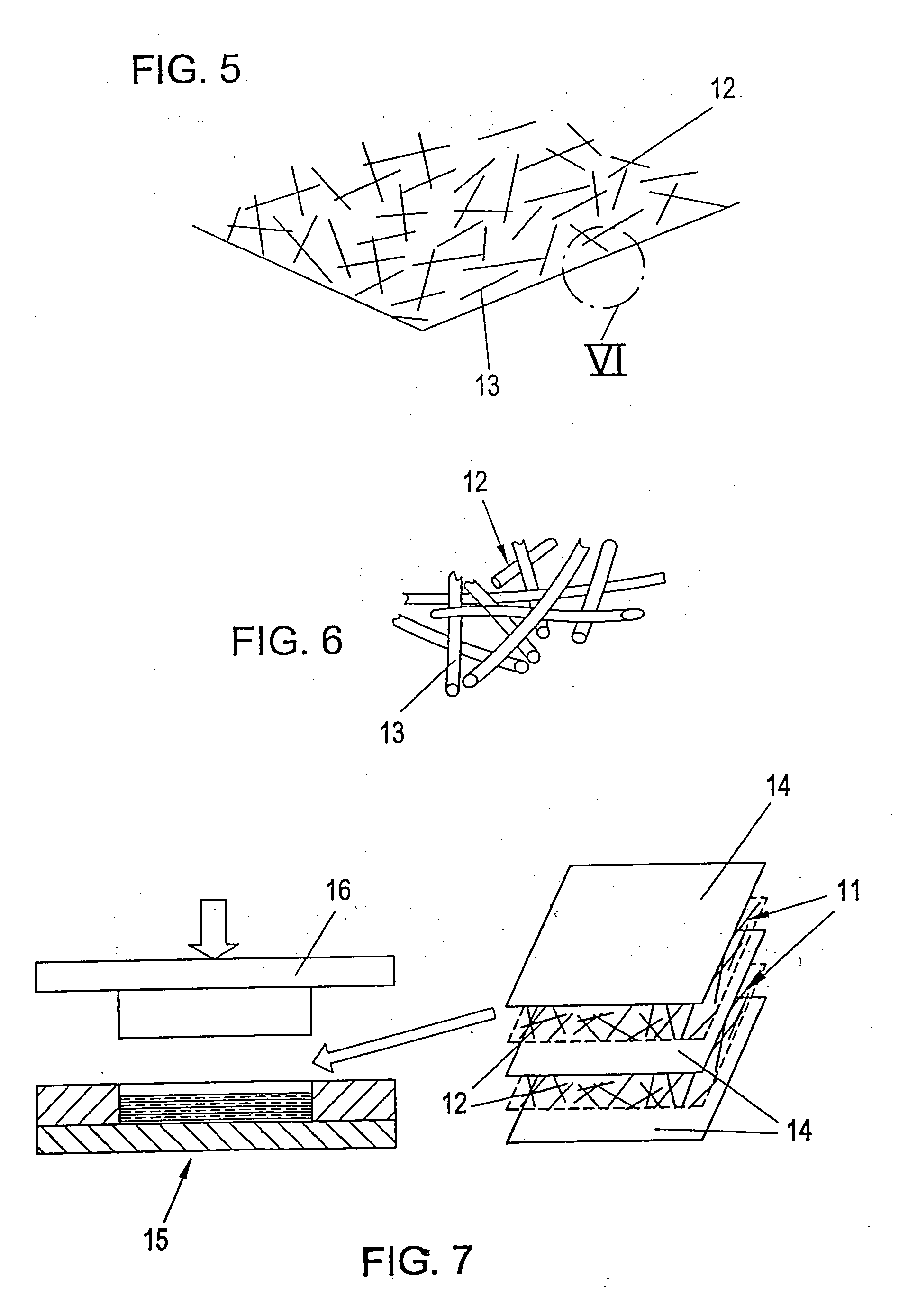
fiber reinforcement is composed of at least one piece of an essentially flat, non-woven fiber fabric, which has, at least in its plane, a directionally independent (random)
fiber orientation, in general. Such non-woven fiber fabrics (called aptly non-woven fiber fabrics in the English language) are made of individual fibers, preferably having a length of at least more than 2 mm for the most part, especially preferred at least more than 4 mm for the most part, and include no binding agents, bonding agents, agglutinants or cements (either they contain no such agents when made or such agents are removed by heating prior to soaking with synthetic material of the invention). The individual fibers are randomly oriented in a plane and have possibly a minor preferred orientation associated with the manufacturing process. Sealing elements, blanks, and semi-finished plates can be manufactured in a
compression molding process thereby and there are generally no limitations relative to the fiber length. The development of
residual stress and events of warping are eliminated by the possible symmetrical and uniform structure. The great fiber length of the individual fibers creates a high reinforcement effect whereby the required rigidity can be realized with a small proportion of fibers. The average proportion of fiber volume lies in the finished sealing element in the range of 5 to 30 percent in an especially preferred embodiment of the invention, preferably in the range of 10 to 20 percent. The favorable damping characteristics of the composite are barely influenced in the direction of the depth of the body. The
low modulus in the direction of the depth of the body enhances, at the same time,
high density and rapid forming of density in the application.
[0011] The even distribution of individual fibers in the non-woven fiber fabrics prevents
delamination at the interfaces and makes very simple impregnation possible, for example, even in case of a polymeric molten
mass of very high
viscosity.
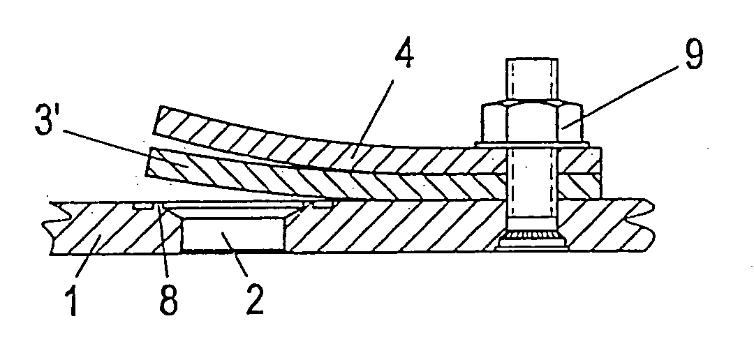
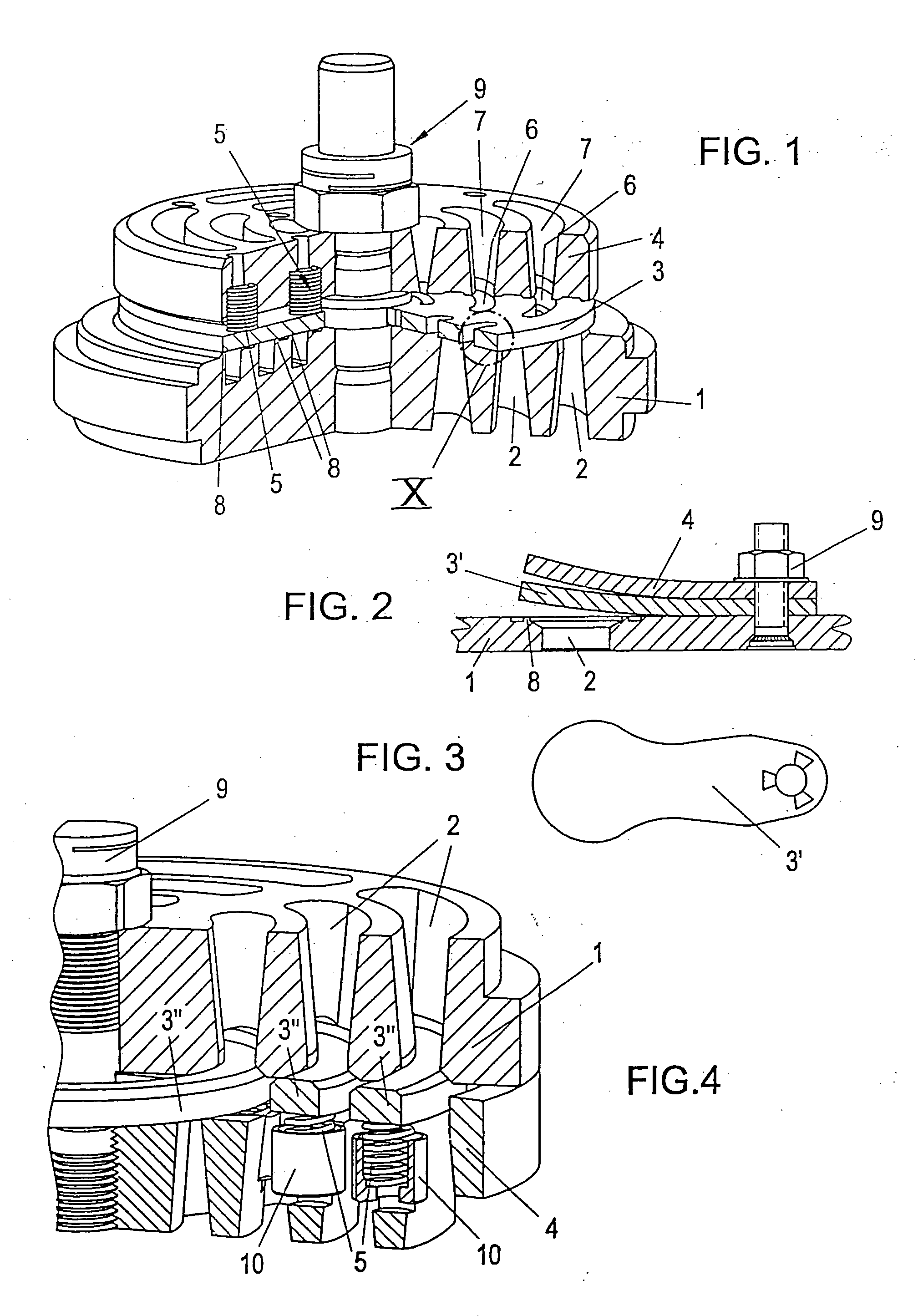
[0016] According to another advantageous embodiment of the invention, the near-surface region of the finished sealing element, which faces the seat surface and / or the surface of the stop element, is free of fiber reinforcement preferably up to a depth that is at least two-times or three-times the size of the
fiber diameter. In automatic compressor valves, and in conjunction with the use of the sealing elements, the development of cracks after near-surface fiber breaks in the proximity of the seat shoulder edge can be avoided and the tribological behavior of the sealing elements can be improved.
[0017] In an additional preferred embodiment of the invention, the fiber-free regions near the surface consist of different material compared to the rest of the sealing element, preferably having a better
toughness and / or high damping characteristics and / or higher resistance against
cracking caused by fatigue. The thereby created functional top
layers serve to reduce spikes in stress at the immediate seat area through additional damping of
impact whereby the development of cracks is prevented in these regions. A microscopic examination of the sealing elements, which are designed without such functional top
layers, show often times that the fibers disposed on the surface—or just below the surface—do not bend at
impact according to the strong deformations in the area of seat shoulders, and they subsequently break, whereby the expansion and joining of microscopic cracks leads to the formation of macroscopic cracks, which leads in turn to malfunctioning of the sealing element. In addition, adhesion of
dirt particles or the like is prevented by the fiber-free functional top layer.
[0019] In a further preferred embodiment of the invention, an intermediate layer, which is disposed between the seat surface and the surface of the stop element, is provided with less fiber reinforcement relative to the neighboring
layers, preferably a decreased proportion of fiber volume compared to the neighboring regions. The characteristic profile of the material or the finished sealing element can thereby be adapted to the respective requirements as well. Rigidity characteristics and damping characteristics can be optimized by varying the proportion of fiber volume throughout the depth of the element, which may be easily achieved by a change in structure during the
compression molding process.

