Pallet cart

a pallet cart and pallet jack technology, applied in the field of pallet carts, can solve the problems of not being able to move pallets long distances, loading pallets typically end up blocking some or all of the operator's forward-looking view, and forklifts are less than ideal for long distances for moving pallets

Inactive Publication Date: 2006-05-18
DANE INDS
View PDF15 Cites 42 Cited by
  • Summary
  • Abstract
  • Description
  • Claims
  • Application Information

AI Technical Summary

Benefits of technology

[0017] In one embodiment, at least one of the castor wheels is normally locked to prevent the castor wheel's rotation about the castor wheel's vertical axis or post. When the coupling mechanism is

Problems solved by technology

Forklifts are less than ideal for moving pallets long distances.
For example, where a forklift is utilized to move a loaded pallet and the forklift is driven forward with the loaded pallet in front of the forklift operator, the loaded pallet typically ends up blocking some or all of the operator's forward-looking view.
Pallet jacks are also less than ideal for moving pallets long distances.
For example, using a pallet jack can require significant physical effort on the part of the pallet jack user.
This can lead to the pallet jack user becoming injured.
While a motorized pallet jack reduces the required physical effort, its visibility issues are not significantly improved over those of the forklift.
Another disadvantage of forklifts and pallet jacks is that most forklifts and pallet jacks will only move a single loaded pallet at one time.
This req

Method used


Image

  • Pallet cart
  • Pallet cart
  • Pallet cart

Examples


Embodiment Construction

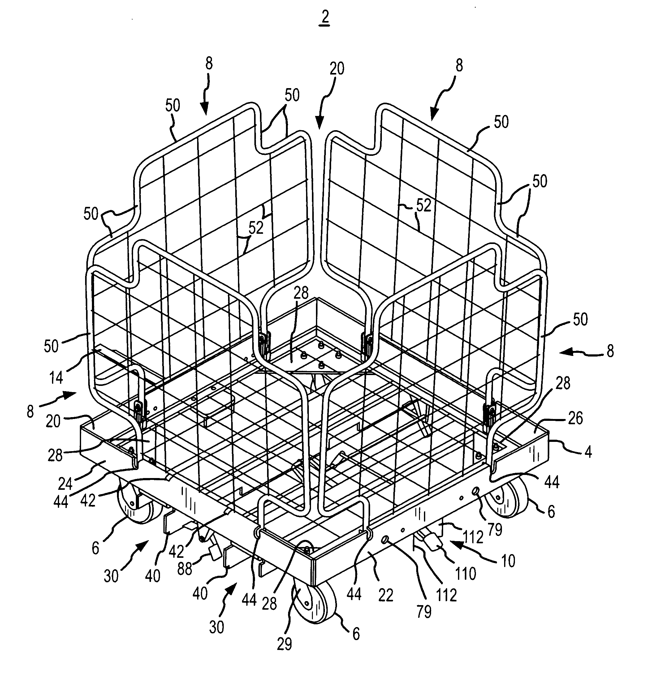
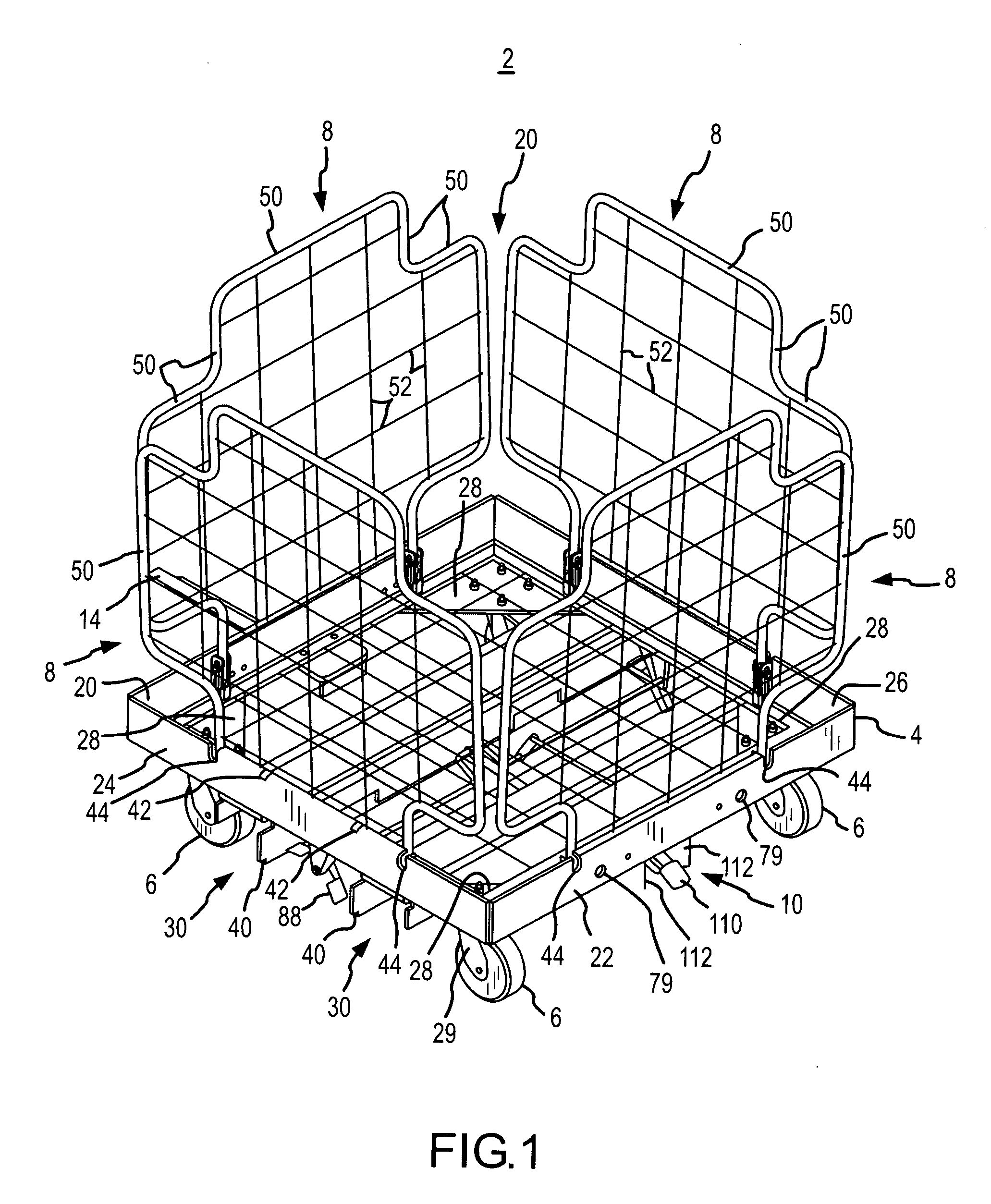
[0036]FIG. 1 is a rear isometric view of one embodiment of the pallet cart 2 of the subject invention. As indicated in FIG. 1, in one embodiment, the pallet cart 2 includes a base frame 4, castors 6, sides 8 and a hitch 10.

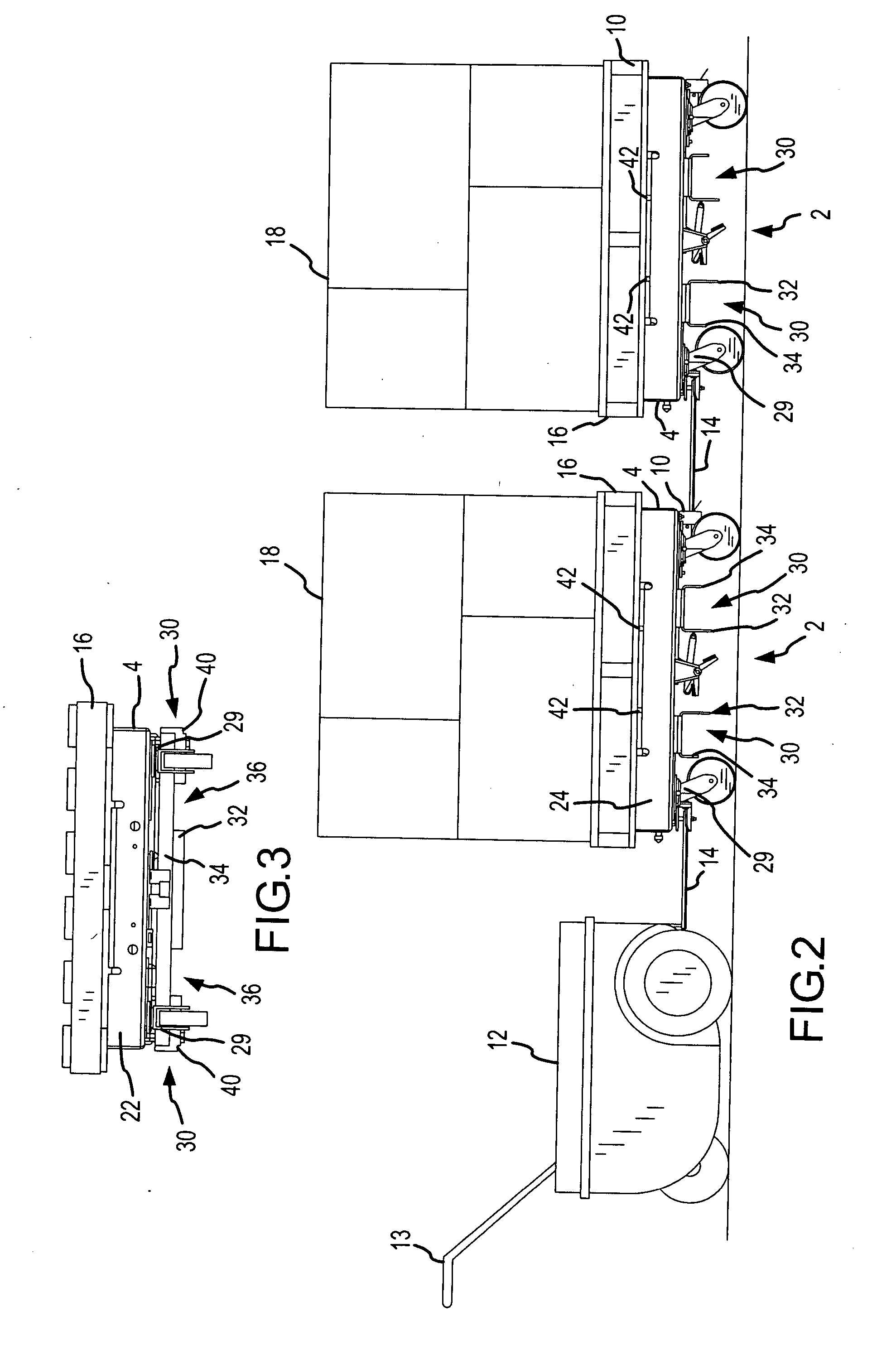
[0037] As indicated in FIG. 2, which is a side elevation of multiple pallet carts 2 hitched in a train-like fashion to a powered pulling device 12, the carts 2 may be equipped with a tongue 14 adapted to hitch to the hitch 10, and the sides 8 may be folded down within the base frame 4 to allow the base frame 4 to serve as a platform on which a pallet 16 may rest. Thus, as can be understood from FIG. 2, one or more carts 2 may be hitched in a string to a powered pulling device 12 for transferring multiple pallets 16 with their respective product loads 18 through a factory, warehouse, retail or similar facility. Also, as can be understood from FIGS. 1 and 2, after the pallets 16 have been delivered to their respective final locations within the facility and the pac...


PUM


Abstract

The present invention is a pallet cart adapted to transport a loaded pallet to a location within a facility and/or transport loose materials from said location. The pallet cart comprises a base frame, a plurality of castor wheels, a first sidewall and a second sidewall. The base frame includes a front frame side, a rear frame side, a hitch, a hitch tongue pivotally extending from the base frame, and a means for coupling the pallet cart to a second pallet cart to form a single extended pallet cart for moving items having an extended length. Each castor wheel is coupled to the base frame and pivotal about an axis extending vertically downward from the base frame. A castor locking mechanism interacts with said means for coupling to prevent a castor wheel from pivoting about its axis when the pallet cart is coupled to a second pallet cart to form an extended pallet cart. The first sidewall is pivotally coupled to the front frame side and adapted to pivot from a vertical position to a horizontal position to be folded within the base frame. Similarly, the second sidewall is pivotally coupled to the rear frame side and adapted pivot from a vertical position to a horizontal position to be folded within the base frame. When the sidewalls are folded down within the base frame, a loaded pallet may be placed on the pallet cart. The pallet cart is adapted to be hitched to a powered pulling device and/or other pallet carts via the hitch tongue. Thus, multiple loaded pallets may be moved in one trip when multiple pallet carts, which are each loaded with a loaded pallet, are hitched in a train-like manner to a powered pulling device that is used to pull the sting of loaded pallet carts to a location within the facility.

Description

CROSS-REFERENCE TO RELATED APPLICATIONS [0001] The present application claims priority to U.S. Provisional Patent Application 60 / 624,520, which was filed Nov. 1, 2004 and is hereby incorporated in its entirety into the present application.FIELD OF THE INVENTION [0002] The present invention relates to devices for, and methods of, transferring products within factory, warehouse and retail facilities. More specifically, the present invention relates to devices for, and methods of, transferring pallets within factory, warehouse and retail facilities. BACKGROUND OF THE INVENTION [0003] Everyday, trucks and railcars deliver products to the loading docks of factory, warehouse and retail facilities throughout the world. Often, these products arrive on pallets or are offloaded onto pallets for distribution throughout the facility. Forklifts or pallet jacks are then utilized to move the pallets to their final locations within facility. [0004] Using a pallet to hold products and then moving th...

Claims


Application Information

Patent Timeline
IPC IPC(8): B62B5/00B60R99/00
CPCB60D1/00B60D1/481B60D2001/005B62B3/16B62B2207/00B62B2207/02B62B2301/0463B62B3/004
Inventor WIFF, JAMES W.DVORAK, ANDREW LEONARD
Owner DANE INDS
Why Eureka
Try Eureka