Optical projection system

a projection system and optical technology, applied in the field of optical projection systems, can solve the problems of large mylars for relatively large objects, difficult measurement, and difficult to determine the exact location of measurement points by technicians

Active Publication Date: 2006-05-18
THE BOEING CO
View PDF20 Cites 105 Cited by
  • Summary
  • Abstract
  • Description
  • Claims
  • Application Information

AI Technical Summary

Benefits of technology

[0011] Therefore, embodiments of the present invention provide an image on the surface of an object being assembled or inspected so as to assist in the assembly or inspection of the object. A projected image that comprises a substantially static two-dimensional image, rather than a moving laser point or line segment, can be use

Problems solved by technology

Depending upon the size and shape of the object, the measurements may be relatively difficult to make.
For manual measurements, technicians often experience difficulty in ascertaining the exact location of measurement points.
Such mylars may be very large for relatively large objects, such as an airplane wing structure.
These mylars can be very expensive to create and maintain, and are also time-consuming to use during the assembly or inspection of the object.
Not only are such laser projectors very expensive, but they are of limi

Method used


Image

  • Optical projection system
  • Optical projection system
  • Optical projection system

Examples


Embodiment Construction

[0016] The present invention now will be described more fully hereinafter with reference to the accompanying drawings, in which some, but not all embodiments of the invention are shown. Indeed, the invention may be embodied in many different forms and should not be construed as limited to the embodiments set forth herein; rather, these embodiments are provided so that this disclosure will satisfy applicable legal requirements. Like numbers refer to like elements throughout.

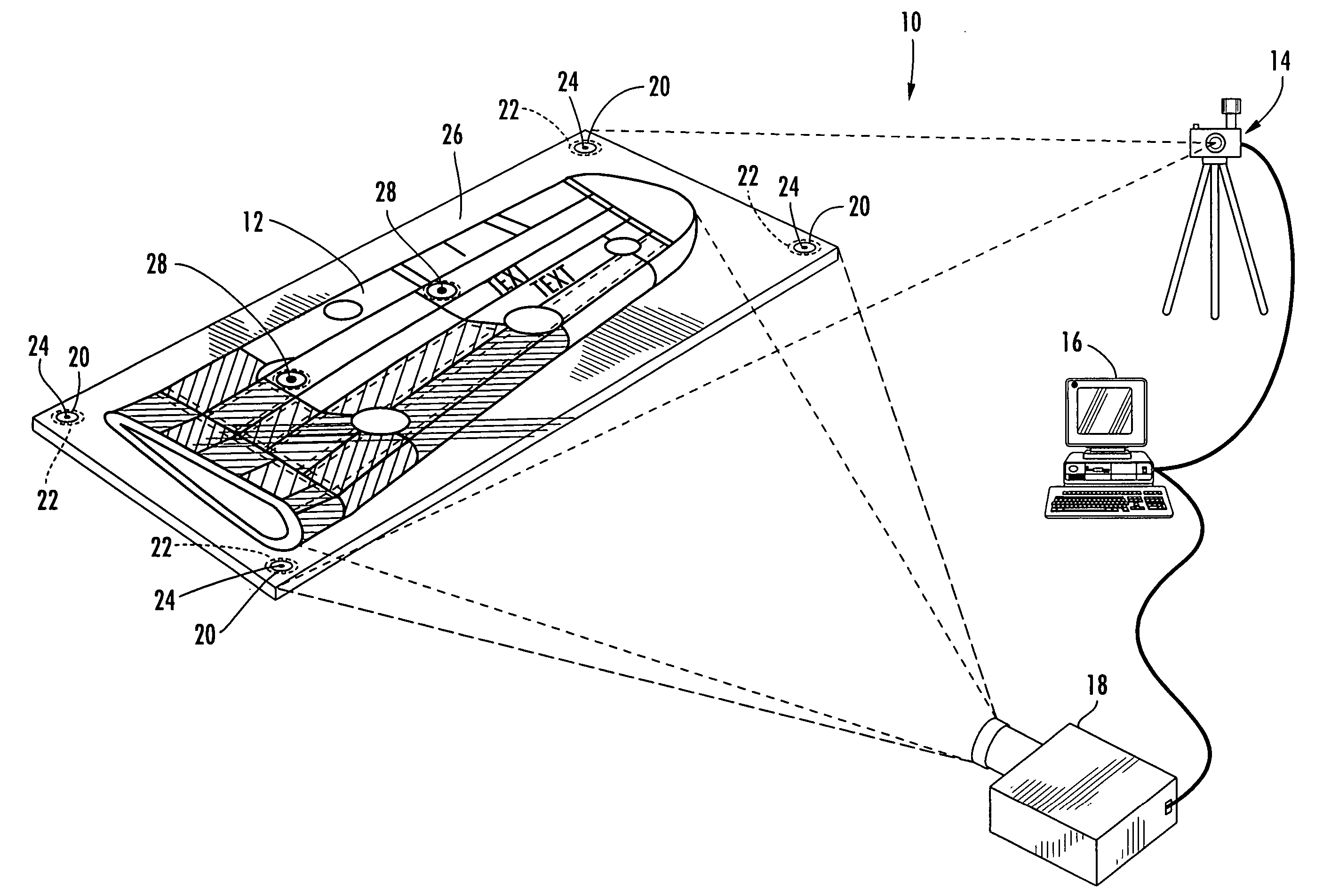
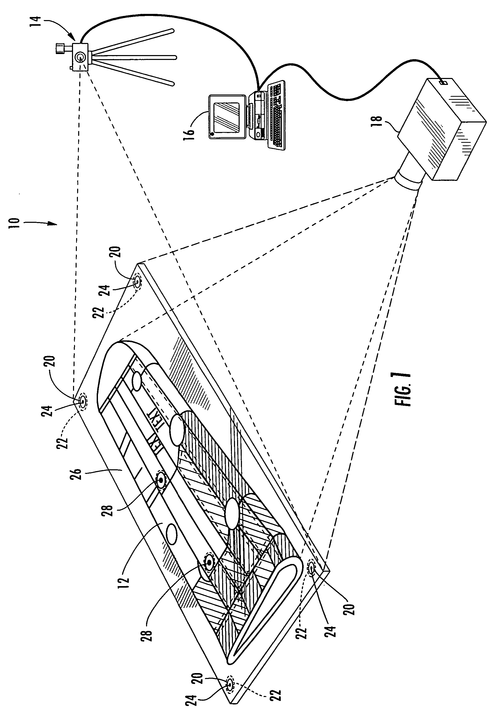
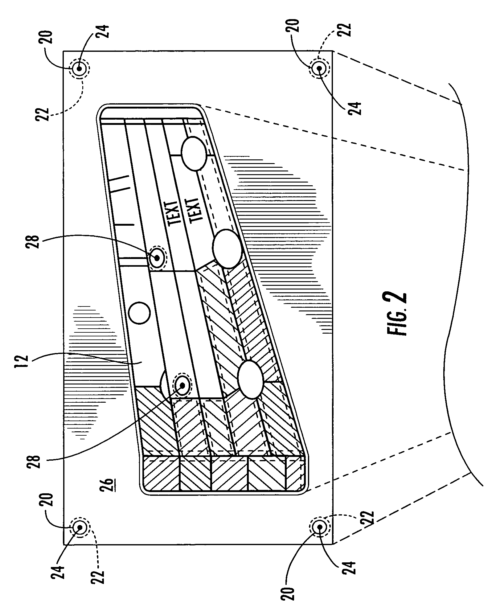
[0017] With reference to FIGS. 1-3, an optical projection system 10 in accordance with one embodiment of the present invention is illustrated. The optical projection system 10 of FIGS. 1-3 is advantageously used for the assembly and inspection of objects; however, it should be appreciated that the present invention may be used in any application wherein optical images are projected. Furthermore, FIGS. 1-2 illustrate the object 12 as being an aircraft wing portion; however, it should be appreciated that the optica...


PUM


Abstract

There is provided an optical projection system for projecting an image onto an object that is being manufactured and/or inspected. The system includes an image-projecting device, a target-locating device for determining the orientation of the image-projecting device relative to the object, and an image-rendering device for rendering the image that is projected onto the object. The target-locating device advantageously comprises a camera that locates at least one target in mechanical communication with the object to determine the orientation of the image-projecting device relative to the object. The image-rendering device advantageously stores a three-dimensional representation of the object that is converted into a two-dimensional image that is projected upon the object. The image projected upon the object is advantageously used during assembly and/or inspection of the object.

Description

BACKGROUND OF THE INVENTION [0001] 1. Field of the Invention [0002] The present invention is related to optical projection systems, and more particularly, to optical projection systems used during the assembly or inspection of objects. [0003] 2. Description of Related Art [0004] During the manufacturing of an object, measurements are typically taken of various parameters of the object and features or details of that object are often located for verification purposes. Depending upon the size and shape of the object, the measurements may be relatively difficult to make. In particular, physical measurements, such as thickness or length, often depend upon the exact locations of the object from which the measurements are taken, most notably with traditional vision systems for measurements. For manual measurements, technicians often experience difficulty in ascertaining the exact location of measurement points. [0005] One method and device for assisting in the measurement of an object is ...

Claims


Application Information

Patent Timeline
IPC IPC(8): G01B11/24B64F5/00
CPCB64F5/0045B64F5/60G01B11/00H04N5/74H04N9/31
Inventor PALMATEER, JOHN W.
Owner THE BOEING CO
Why Eureka
Try Eureka