Device for retaining optical components

Active Publication Date: 2006-05-18
LEICA MICROSYSTEMS CMS GMBH
View PDF8 Cites 12 Cited by
  • Summary
  • Abstract
  • Description
  • Claims
  • Application Information

AI Technical Summary

Benefits of technology

[0009] The result of this is that a ball bearing can click-stop into the detent gently and therefore with little vibration. This is because what occurs is not an abrupt click-stopping after the ball runs over the edge of a V-groove or a rectangular U-groove, but instead a gentle rolling into the detent according to the present invention, which is completed when the ball has reached the more strongly curved region of the detent. Provision can be made here either for the ball to be partly surrounded by the more strongly curved region of the detent (i.e. by the inner profile), or for the ball to rest on the edges of the inner profile, i.e. at the point where the inner profile transitions into the outer profile. It is necessary in any case to ensure that the positioning as a result of the click-stopping remains stable and is maintained without play, but on the other hand that when the

Problems solved by technology

This is accompanied by the quietest possible working nois

Method used


Image

  • Device for retaining optical components
  • Device for retaining optical components
  • Device for retaining optical components

Examples


Example

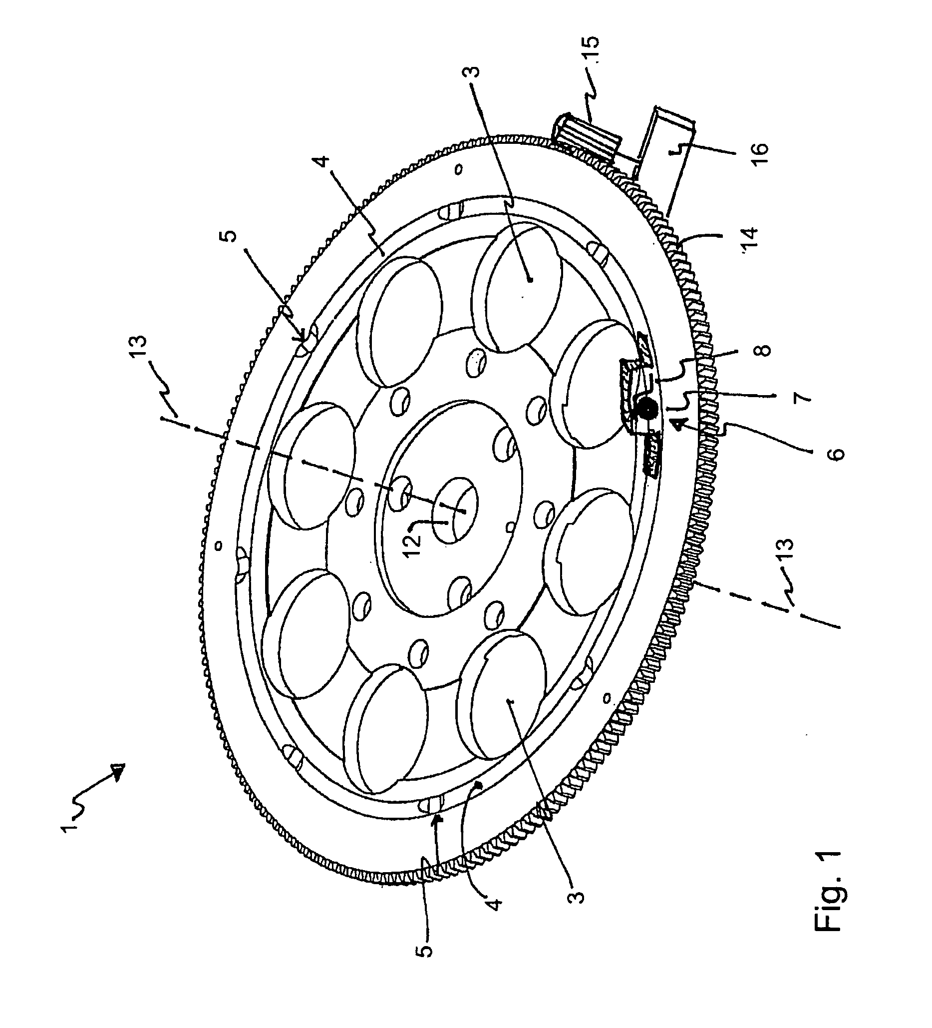
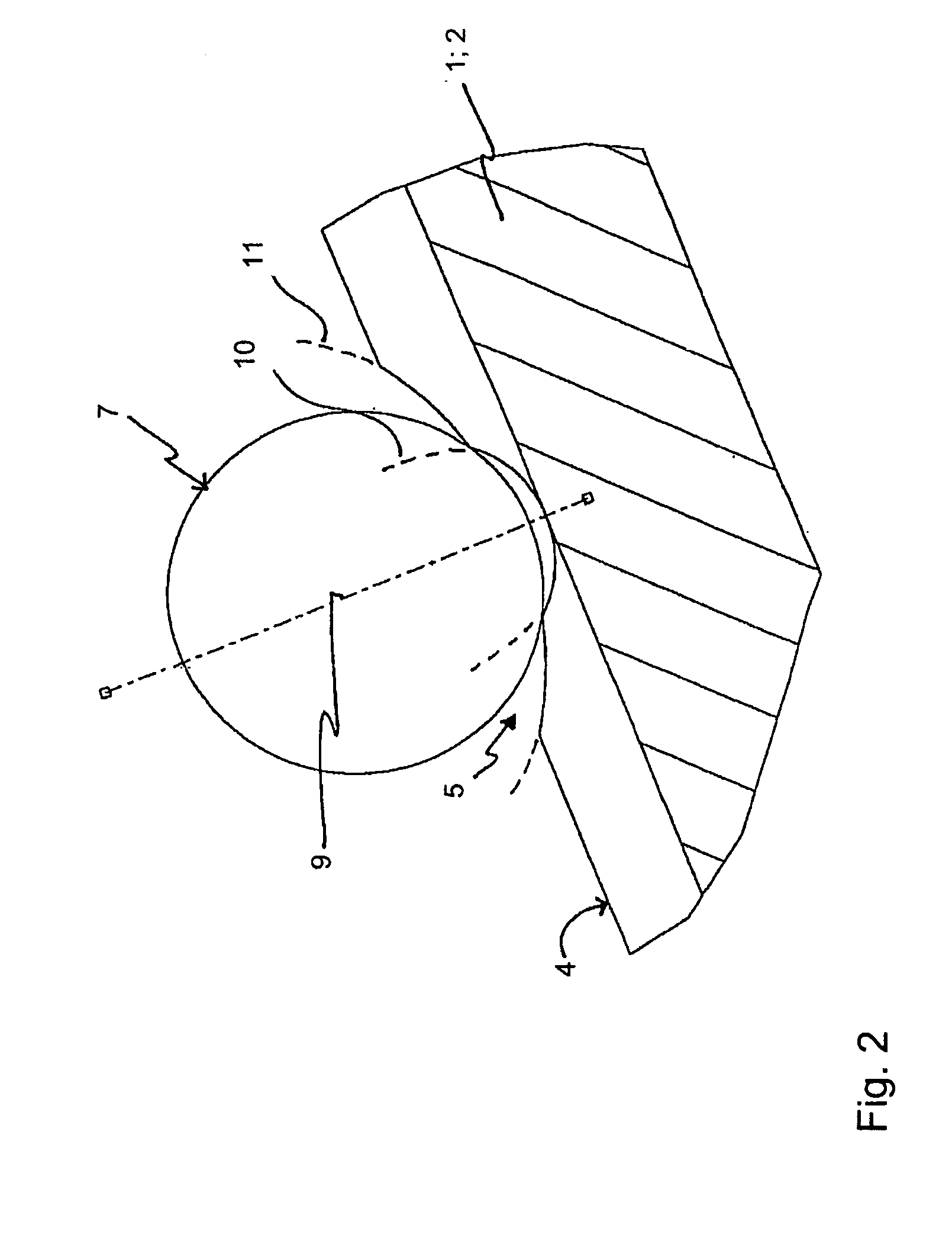
[0030]FIG. 1 is a perspective sketch of a rotary disk according to the present invention for retaining optical components. Rotary disk 1 comprises at its center an opening 12 for a rotation axis 13, open orifices 3, in this exemplifying embodiment eight in number, being arranged on a circular path concentric with rotation axis 13. A raceway 4, concentric with rotation axis 13 and having eight detents 5, is provided on rotary disk 1. The detents guarantee highly accurate positioning of rotary disk 1, thereby ensuring that optical components (for example fluorescence filter blocks) retained on rotary disk 1 can be brought into an exact position in an optical device (e.g. a fluorescence microscope) and held there.

[0031] Rotary disk 1 depicted in FIG. 1 can be rotated in motor-driven fashion about rotation axis 13. Provided for that purpose on the outer rim of rotary disk 1 is a tooth set 14 into which engages a pinion 15 to which, in turn, a rotary motion is imparted by a drive motor ...


PUM


Abstract

The invention relates to a device, such as a rotary disk (1) or a longitudinal slider (2), for retaining optical components, this device comprising open orifices (3) arranged next to one another, and a raceway (4) having detents (5) being provided in the direction of the arranged orifices (3), which detents are embodied in such a way that they are to be brought into click-stop engagement with a ball bearing (6) running along the raceway (4), in order to hold the device (1, 2) in a selected position. In order to enable gentle click-stopping of the ball bearing (6) with a wide capture region, it is proposed that the detents (5) have, in the running direction, a profile comprising a combination of two arc-shaped profiles (10, 11), such that an outer profile (11) of lesser curvature surrounds an inner profile of greater curvature (10).

Description

CROSS REFERENCE TO RELATED APPLICATIONS [0001] Priority is claimed to German patent applications 10 2004 050 639.6 and 10 2004 061 901.8, the entire subject matters of both of which are hereby incorporated by reference herein.FIELD OF THE INVENTION [0002] The invention relates to a device for retaining optical components, the device comprising open orifices arranged next to one another, and a raceway having detents being provided in the direction of the arranged orifices, which detents are embodied in such a way that they are to be brought into click-stop engagement with a ball bearing circulating along the raceway, in order to hold the device in a selected position. The invention relates in particular to a rotary disk for retaining optical components, the rotary disk comprising in its center an opening for a rotation axis, open orifices being arranged on a circular track concentric with the rotation axis, and a raceway concentric with the rotation axis and having detents being prov...

Claims


Application Information

Patent Timeline
IPC IPC(8): G02B21/00
CPCG02B7/16Y10T74/19749G02B21/248
Inventor JAGEMANN, OLIVER
Owner LEICA MICROSYSTEMS CMS GMBH
Why Eureka
Try Eureka