
Imaging optical system with focusing function

Inactive Publication Date: 2006-05-18
FUJI PHOTO OPTICAL CO LTD
View PDF3 Cites 13 Cited by
  • Summary
  • Abstract
  • Description
  • Claims
  • Application Information

AI Technical Summary

Benefits of technology

[0006] The fluid lens as described in the above Philips Research Press Release can change a focal length without mechanically moving the lens using a motor or the like. If such a lens system can be applied to focusing technology, it is advantageous in terms of ease of miniaturization and configuration.
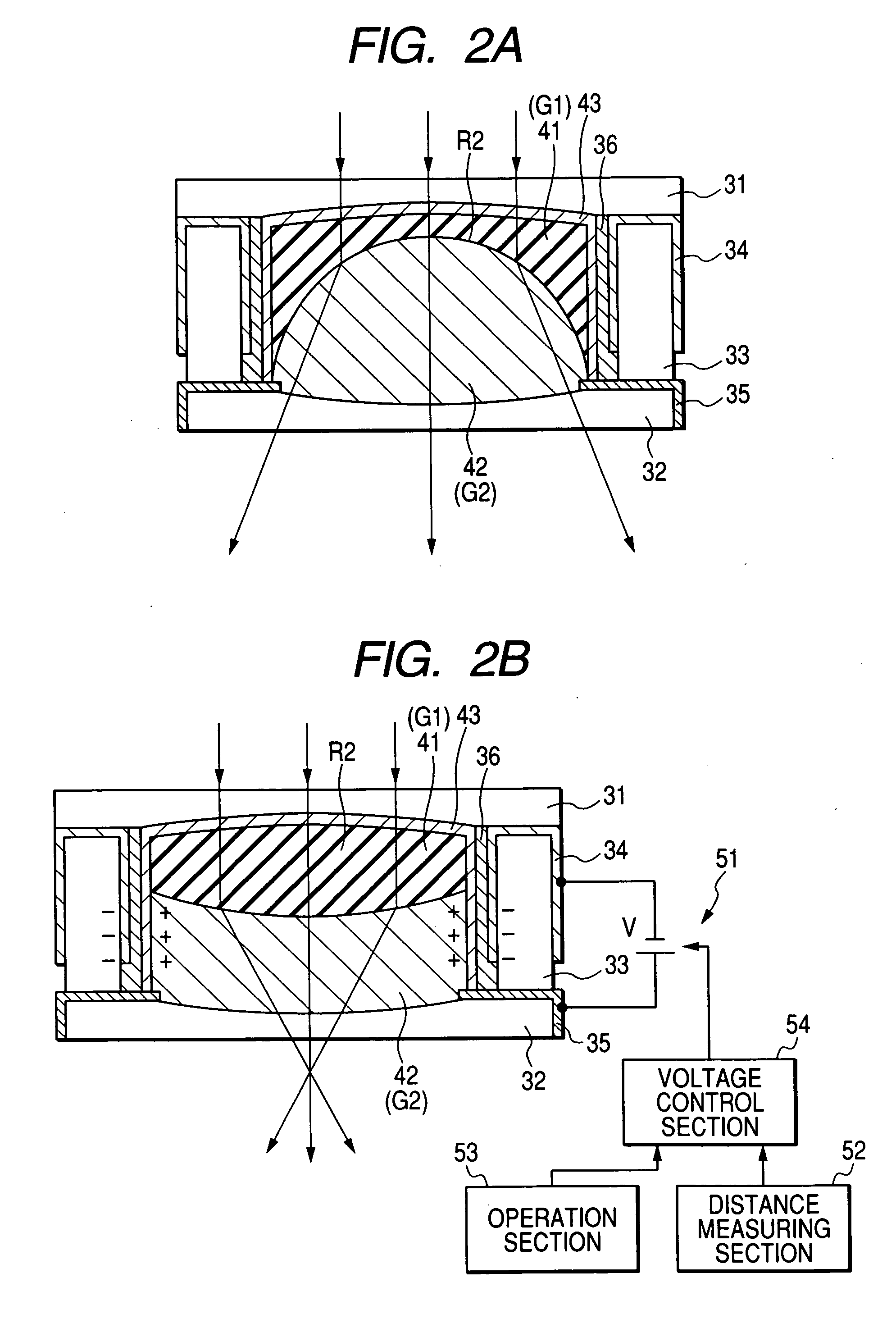
[0008] An imaging optical system with a focus function of the present invention has a power as a whole and performs focusing using a focusing cemented lens whose cemented surface has a variable shape. The cemented surface shape of the focusing cemented lens is electrically controlled. Focusing is achieved by controlling the cemented surface shape, depending on a distance from an object. Since focusing is performed without mechanically moving a lens using a motor or the like, it is advantageous in terms of ease of miniaturization and configuration. In this case, the focusing cemented lens is advantageous in terms of efficient focusing and manufacture when the conditions represented by expressions (1) to (3) are satisfied over the entire focus region.

Problems solved by technology

However, in such apparatuses, a demand for image quality is growing year after year.
Therefore, a lens moving mechanism is required, which is disadvantageous in terms of ease of miniaturization and configuration.

Method used


Image

  • Imaging optical system with focusing function
  • Imaging optical system with focusing function
  • Imaging optical system with focusing function

Examples


examples

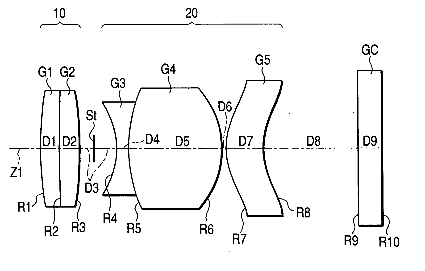
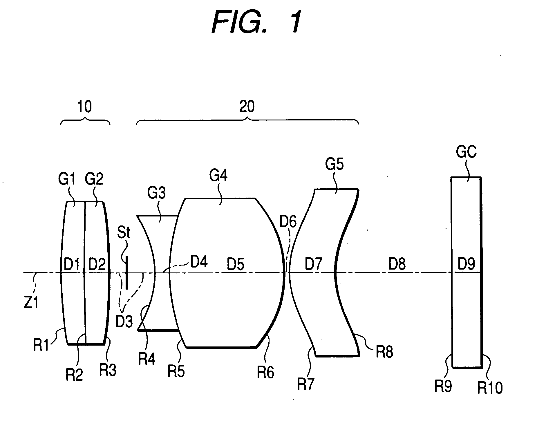
[0032] Next, specific numerical value examples of the imaging optical system of the embodiment of the present invention will be described. FIGS. 3A and 3B illustrate specific lens data corresponding to the structure of the imaging optical system of FIG. 1. FIG. 3A illustrates a basic data portion of the lens data FIG. 3B illustrates a data portion concerning an aspherical shape of the lens data.

[0033] In the lens data, a column for surface numbers Si indicates the number of an i-th (i=1 to 10) lens element surface, where a lens element surface closest to an object is the first lens element surface, and i is successively increased toward an image. A column for radii of curvature Ri indicates the value of the radius of curvature of the i-th surface counted from an object, corresponding to reference character Ri of FIG. 1. A column Di for surface intervals indicates an interval on an optical axis between the i-th surface Si and the i+1-th surface Si+1counted from an object. The radius...


PUM


Abstract

An imaging optical system is provided and has a focusing section including a cemented lens (first and second lenses), which includes first and second fluid materials having different refractive indices from each other; and whose cemented surface shape can be electrically controlled. A refractive index Nd1 of the first fluid material, a refractive index Nd2 of the second fluid material, a minimum value RA of a radius of curvature of the cemented surface of the cemented lens, a focal length fa of the whole cemented lens, and a focal length f of the whole lens system satisfy the conditions specified in the specification.

Description

FIELD OF THE INVENTION [0001] The present invention relates to an imaging optical system with a focus function which is used for focusing technology in various cameras, cellular phones with a camera, and the like. BACKGROUND OF THE INVENTION [0002] Cameras and camcorders with an autofocus function have been known. In these imaging apparatuses, focusing is generally performed by moving the whole or a part of a lens system of an imaging lens using a drive systems such as a motor or the like. On the other hand, in recent years, a number of small-size information terminal apparatuses, such as a cellular phone, a personal digital assistant (PDA), and the like, which includes an imaging module to have an imaging function, are becoming available on the market. Imaging optical systems in these information terminal apparatuses often employ pan focus, in which the depth of field of a lens is utilized, as a focusing method in favor of ease of miniaturization and configuration. [0003] Recently,...

Claims


Application Information

Patent Timeline
IPC IPC(8): G02B15/14
CPCG02B3/14G02B26/005H04N5/2254H04N5/23212
Inventor SHINOHARA, YOSHIKAZUSATO, KENICHI
Owner FUJI PHOTO OPTICAL CO LTD
Learn More