
Device and

a technology of positron emission tomography and device, which is applied in the field of nuclear medicine, can solve the problems of limited irradiation intensities for producing radioisotopes, power dissipation, and limitations in the intensity and/or energy of particle beams that are used,

Active Publication Date: 2006-05-18
ION BEAM APPL
View PDF19 Cites 33 Cited by
  • Summary
  • Abstract
  • Description
  • Claims
  • Application Information

AI Technical Summary

Benefits of technology

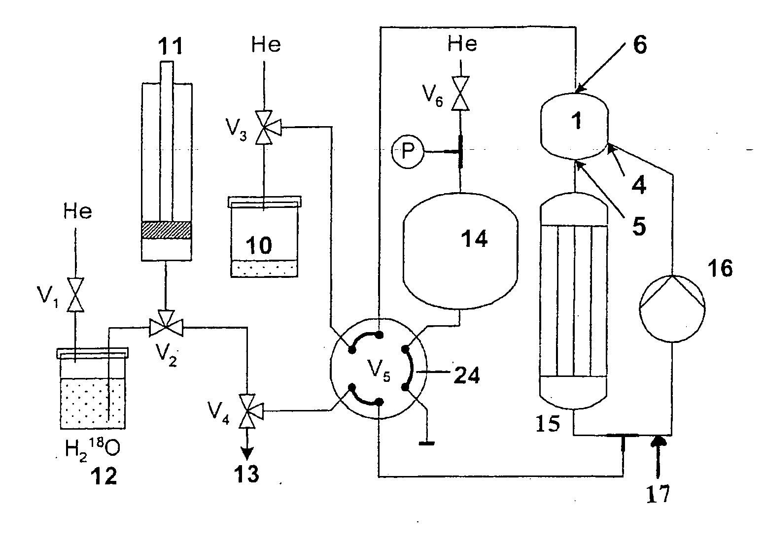
[0024] The present invention aims to provide a device and a method for producing a radioisotope of interest, such as 18F, from a target material irradiated with a beam of accelerated particles that do not have the drawbacks of the devices and methods of the prior art.
[0026] It is another aim of the present invention to provide a device and a method which ensure a maximal heat exchange in operating conditions, that means during the irradiation and thus the production of said radioisotope of interest.

Problems solved by technology

However, the power dissipated by the target material irradiated by the accelerated particle beam limits the intensity and / or the energy of the particle beam that it is used.
Moreover, in the case of 18F radioisotope production, given the particularly high cost of 18O-enriched water, only a small volume of this target material, at the very most a few millilitres, is placed in the cavity.
Thus, the problem of dissipating the heat produced by the irradiation of the target material over such a small volume constitutes a major problem to be ovecome.
More generally, given this problem of heat dissipation by the target material, the irradiation intensities for producing radioisotopes are currently limited to 40 μA for an irradiated target material volume of 2 ml.
The possibilities afforded by current cyclotrons are therefore indubitably underexploited.
However, in that device, the target material is static, which gives said device configured in this way a number of drawbacks insofar as the heat dissipation in this configuration is physically limited due to the coefficient of heat exchange of the liquid with its container.
Moreover, because of the high temperatures that are reached in the sealed cavity, the entire device must be pressurized.
In fact, it is practically impossible to “monitor” the amount of 18F produced in such a device, and the result, in terms of activity and yield, is therefore only known a posteriori.
Nevertheless, that device and method did not use pressurizing means so that the control of the pressure is a real problem in such a device.
Moreover, said device and method were not explained in detail and are in practice prone to major technical implementation difficulties.

Method used


Image

  • Device and
  • Device and
  • Device and

Examples


first embodiment

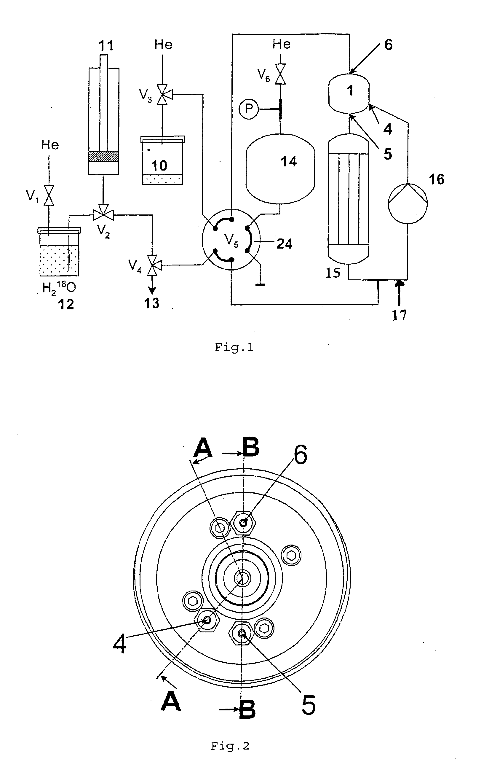
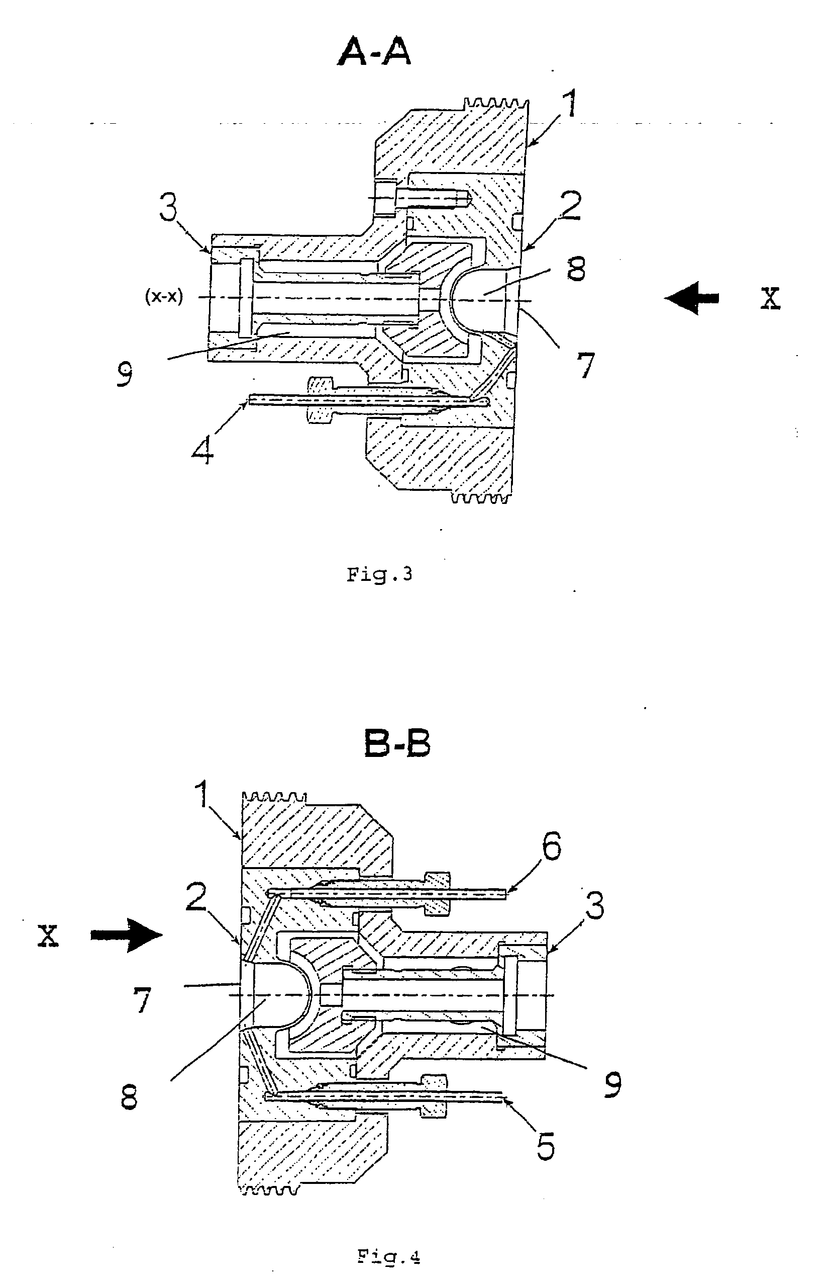
[0069] the irradiation cell 1 is disclosed in FIG. 2 to 4 and corresponds to the mechanical assembly which, during operation of said device, is subjected to an accelerated particle beam irradiation on the target material in order to produce the radioisotope of interest.

[0070] The irradiation cell 1, as represented in FIG. 2 to 4, comprises an insert 2 which consists in one or more metallic parts (elements) arranged so as to create a volume corresponding to an irradiation cavity 8.

[0071] The insert 2 therefore includes the cavity 8, this cavity has a configuration such that it can house the target material which is subjected to the bombardment of the accelerated particle beam. For this purpose, said cavity is closed (sealed) by an irradiation window 7 transparent to the accelerated particle beam.

[0072] The irradiation cell also comprises an inlet 4 and an outlet 5 allowing the target material to enter the irradiation cell and get out of it. The inlet and outlet provide the inflow a...

second embodiment

[0078] detailed in FIG. 5 to 7, the inlet 4 is located approximately in the direction of the impact point of the accelerated particle beam X, i.e. said inlet 4 corresponds essentially to the central symmetry axis (x-x) of the irradiation cell 1, while the outlet ducts 5 and 6 are located at the edge (periphery) of said cell.

[0079] This embodiment allows to create a vortex inside said cavity, again essentially without stagnation areas. Furthermore, the fact that the inlet duct is located approximately facing the impact point of the beam allows a displacement tolerance of about 1 mm for said beam.

[0080] Moreover, in a particularly advantageous way, this second embodiment allows to give a symmetric circulation to the target material within said cavity 8. Similarly, the fact that the inlet duct 4 is facing the irradiation window in the opposite direction of the irradiation beam X allows to induce a cooling of said window and thus prevent an excessive heating of the window by the accel...


PUM


Abstract

The present invention is related to a device and a method for producing a radioisotope of interest from a target fluid irradiated with a beam of accelerated charged particles, the device includes in a circulation circuit (17): an irradiation cell (1) having a metallic insert (2) able to form a cavity (8) designed to house the target fluid and closed by an irradiation window (7), the cavity (8) including at least one inlet (4) and at least one outlet (5); a pump (16) for circulating the target fluid inside the circulation circuit (17); an external heat exchanger (15); the pump (16) and the external heat exchanger (15) forming external cooling means of the target fluid; the device means for pressurizing (14) of the circulation circuit (17) and the external cooling means of the target fluid are arranged in such a way that the target fluid remains inside the cavity (8) essentially in the liquid state during the irradiation.

Description

FIELD OF THE INVENTION [0001] The present invention relates to a device and to a method for producing radioisotopes, such as 18F, by irradiating with a beam of charged particles a target material which includes a precursor of said radioisotope. [0002] One of the applications of the present invention relates to nuclear medicine, and in particular to positron emission tomography. TECHNICAL BACKGROUND AND PRIOR ART [0003] Positron emission tomography (PET) is a precise and non-invasive medical imaging technique. In practice, a radiopharmaceutical labelled by a positron-emitting radioisotope, in situ disintegration of which results in the emission of gamma-rays, is injected into the organism of a patient. These gamma-rays are detected and analyzed by an imaging device in order to reconstruct in three dimensions the biodistribution of the injected radioisotope and to obtain its tissue concentration. [0004] Fluorine 18 (T1 / 2=109.6 min) is the only one of the four light positron-emitting r...

Claims


Application Information

Patent Timeline
Patent Type & Authority Applications(United States)
IPC IPC(8): G21G1/10G21C23/00G21K5/08
CPCG21G1/10
Inventor JONGEN, YVESCOMOR, JOZEF
Owner ION BEAM APPL
Learn More