
Partial oxidation reactor

Inactive Publication Date: 2004-08-05
INST FR DU PETROLE
View PDF7 Cites 22 Cited by
  • Summary
  • Abstract
  • Description
  • Claims
  • Application Information

AI Technical Summary

Benefits of technology

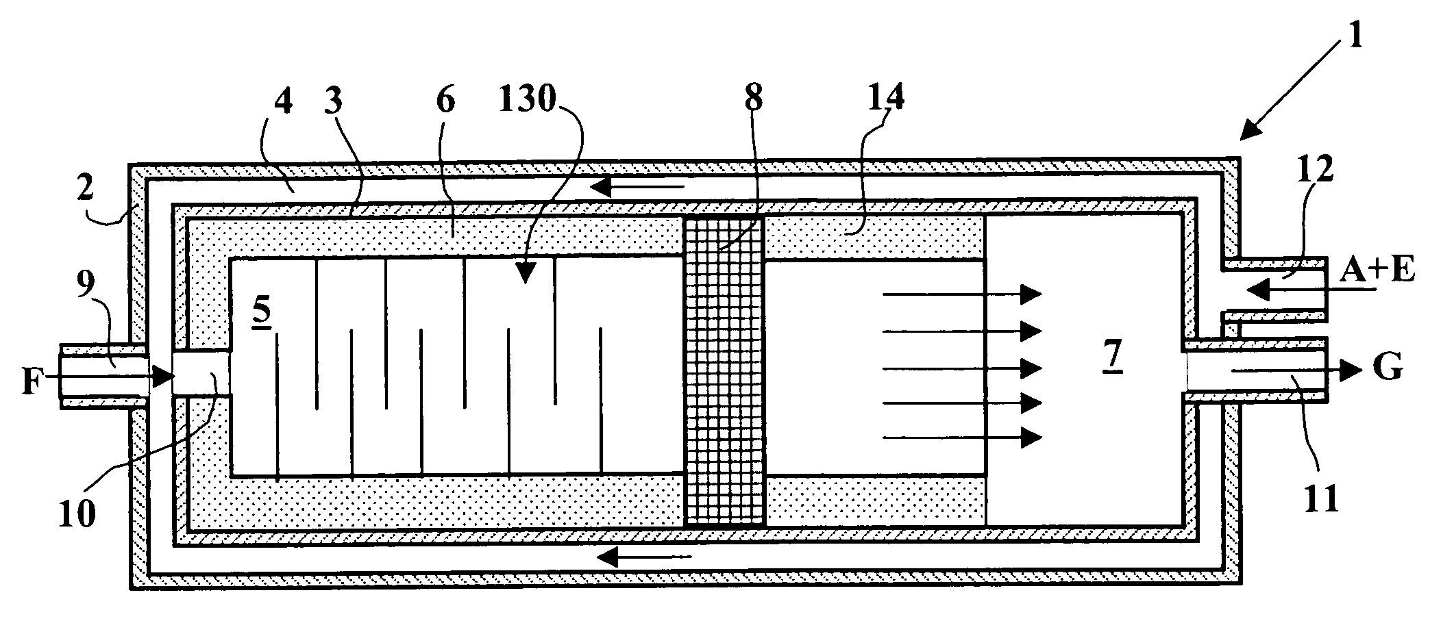
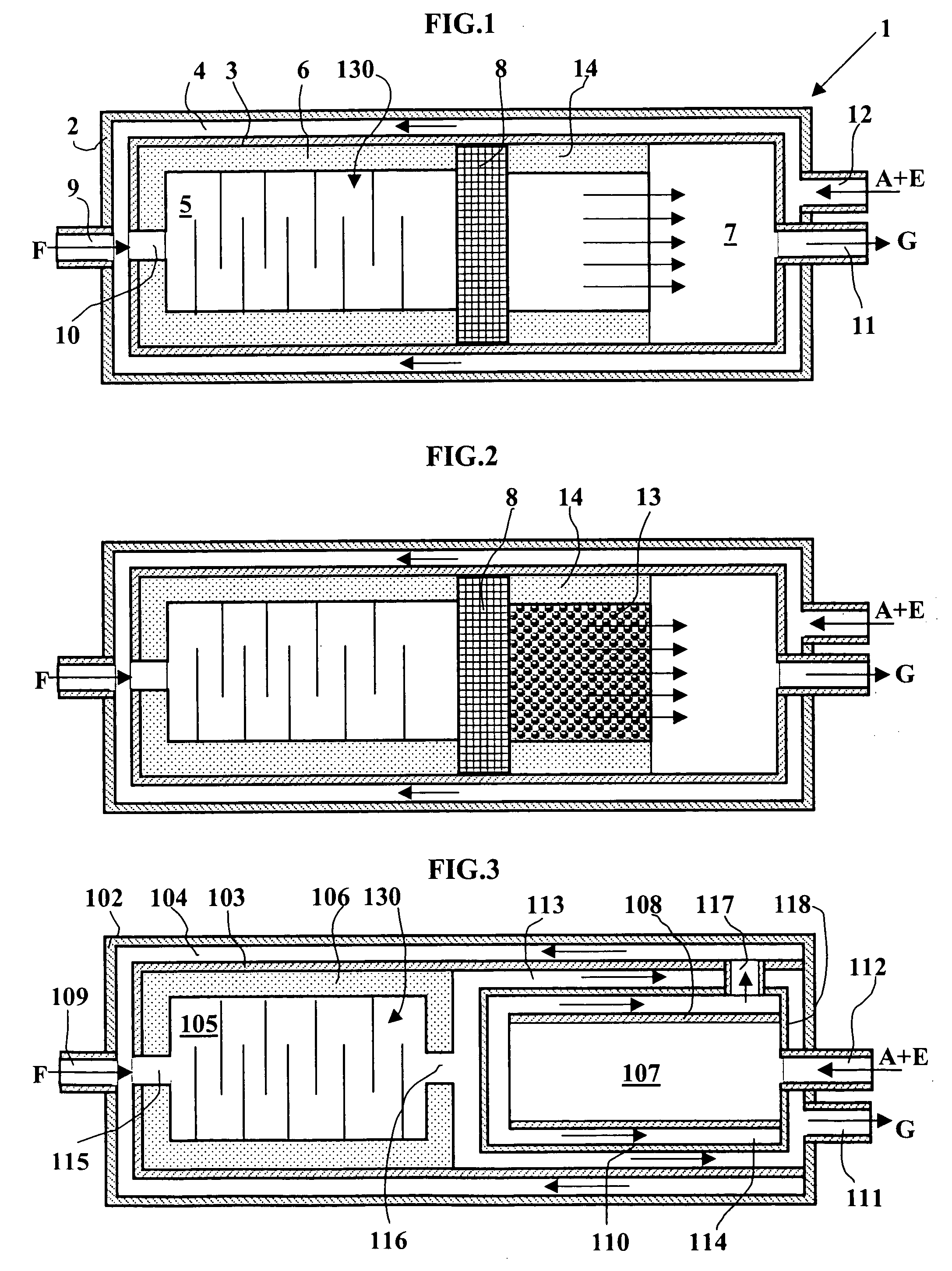
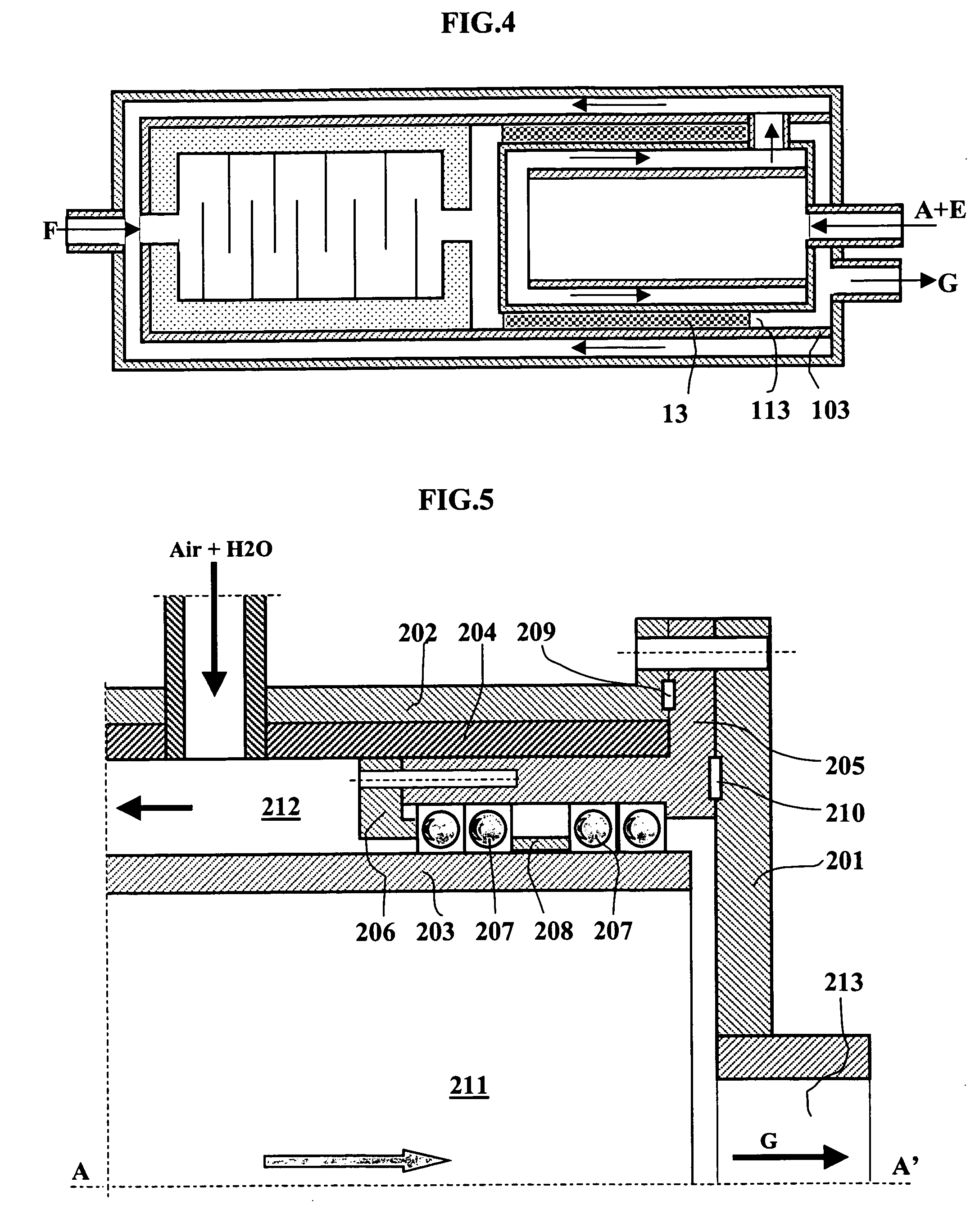
[0039] Preferably, the first reaction chamber is adiabatic and the second reaction chamber consists of two zones, a fist zone that is also adiabatic, and a second zone that promotes a significant heat exchange between the cold gas that contains oxygen, generally air, optionally with an addition of water vapor, and warm effluents from the reaction so as to quickly cool the latter.
[0044] The purpose of the first perfect-mixing reaction chamber is to carry out combustion without a flame front, which makes it possible to limit the local temperatures and to operate with a homogeneous richness, creating a significant reduction in soot formation.
[0046] The second piston and adiabatic reaction chamber makes it possible to eliminate the last traces of unconverted hydrocarbons, in particular the hydrocarbons such as methane, and the acetylene compounds that have been formed in the first perfect-mixing reaction chamber. The sizing of the second reaction chamber with piston flow is directly linked to the operating temperature. For a temperature of 1600.degree. C., a dwell time of, for example, 0.05 to 0.3 second will be selected. The dwell time can be increased if the temperature is lowered.

Problems solved by technology

This concept may very likely lead to a limitation of the soot production because of the premixing and the oxidation of heavy molecules of the fuel that are produced in the cold flame, but it imposes very significant limitations on the preheating temperature of the air and the fuel.
Actually, beyond 480.degree. C. in the cold flame and therefore from a preheating of the air-fuel mixture that is higher than about 350.degree. C., there is a risk of losing control of the reaction and a return of flame into the cold flame chamber.
This limitation of the preheating produces a very significant economic penalty because a large fraction of the fuel is then to be oxidized to reach the reaction temperature, which greatly penalizes the yield of the generator relative to a system where it would be possible to preheat the air to more than 1000.degree. C. before the input into the combustion zone.
At this temperature, the reaction times are relatively significant, on the order of several seconds, and there is a risk of obtaining relatively large methane concentrations in the effluents of the POX.

Method used


Image

  • Partial oxidation reactor
  • Partial oxidation reactor
  • Partial oxidation reactor

Examples


example 2 (

ACCORDING TO THE INVENTION)

[0127] A reactor-exchanger according to FIG. 6 of this invention is supplied by the same amounts of butane, on the one hand, and by a mixture of air and water vapor, on the other hand. The butane is preheated to 450.degree. C. in the same external exchanger as in the preceding example.

[0128] The H2O / C molar ratio is set as in the preceding example at 0.2.

[0129] The temperature for preheating the air and the water vapor results from a heat exchange with the effluents of the reaction zone according to the diagram of FIG. 6.

[0130] The flow rate of air entering via pipe (312) is set so as to reach a temperature of 1600.degree. C. in first reaction chamber (305), and the ratio between the flow rate of entering air and the flow rate of stoichiometric air is 0.34.

[0131] While the heat exchange between the effluents of the reaction and the mixture of air and water vapor has taken place over the entire path (304), (305), (306) and (307), the air-water vapor mixture...


PUM

PropertyMeasurementUnit
Fractionaaaaaaaaaa
Fractionaaaaaaaaaa
Timeaaaaaaaaaa

Abstract

A new type of reactor that is intended to carry out partial oxidation reactions starting from liquid feedstocks that can go from GPL to gas oil for the purpose of producing synthesis gas is described. This reactor is characterized by finely controlled hydrodynamics and a high degree of thermal integration.

Description

Technological Background[0001] This invention relates to the field of reactors that are intended to carry out non-catalytic partial oxidation reactions starting from very diverse hydrocarbon fractions for the purpose of producing a mixture of carbon monoxide (CO) and hydrogen (H2) that is called synthesis gas. The reactors that are targeted by this invention are more particularly intended for small-capacity applications as opposed to standard industrial applications such as Fischer-Tropsch synthesis or ammonia synthesis.[0002] In this case, installed thermal powers of between 0.1 kW and 1000 kW are considered. The targeted markets are then the supply of hydrogen-rich gas for fuel-cell-type (PAC) applications or hydrogen enrichment of thermal engines.[0003] In the text below, this type of reactor will be called a POX reactor, the usual abbreviation of partial oxidation reactions.[0004] The use of a partial oxidation reactor for carrying out the generation of synthesis gas, and more p...

Claims


Application Information

Patent Timeline
IPC IPC(8): B01J8/02B01J19/00B01J19/24C01B3/36H01M8/06
CPCB01J8/0221C01B2203/1282B01J19/006B01J19/244B01J2208/00495B01J2208/0053B01J2208/00557B01J2219/00085B01J2219/00094B01J2219/00155B01J2219/00768B01J2219/182B01J2219/185B01J2219/187C01B3/36C01B2203/0255C01B2203/0883C01B2203/1241C01B2203/1247B01J8/0285Y02P20/129
Inventor NOUGIER, LUCBERTHOLIN, STEPHANENASTOLL, WILLY
Owner INST FR DU PETROLE
Learn More