Multimodal biometric platform

Active Publication Date: 2006-05-18
IMAGEWARE SYST
View PDF6 Cites 174 Cited by
  • Summary
  • Abstract
  • Description
  • Claims
  • Application Information

AI Technical Summary

Benefits of technology

[0010] The biometric matching engines are organized into groups, based upon their capabilities. Each biometric matching engine of a group can process the same types of biometrics. A biometric matching engine may belong to more than on group.
[0011] According to the present invention, all communication between the biometric clients and the biometric matching engines goes through the router. The biometric clients and the biometric matching engines see only the router. During an enrollment phase, the biometric clients send biometric and demographic data to the router. The router stores the demographic data and sends the biometric data to a biometric matching engine of an appropriate group. The plugins of the biometric matching engine convert the images of the biometric data to templates and send the templates back to the router. The router sends the templates back to one or all of the biometric matching engines of the group, depending on the configuration of the system. The system may be configured for striped operation, in which case, the templates are sent to one biometric matching engine of the group. In the striped configuration, the router uses a load balancing scheme to ensure that each biometric matching engine of a group has approximately the same number of enrolled templates in its cache. Alternatively, the system may be configured for mirrored operation. In the mirrored configuration, router sends the templates to each biometric matching engine of the group. In either configuration, the biometric matching engines cache the enrolled templates they receive from the router, preferably in physical memory.

Problems solved by technology

A problem in current biometric identification and authentication is “spoofing”, which amounts to tricking the biometric capture device.
The device may capture the counterfeit image and then identify the wrong individual.
However, biometrics tend to be independent of each other so that it is unlikely that individuals that match on one biometric would match on multiple biometrics.
However, there are a number of problems with current attempts to provide a multimodal biometric platform.

Method used


Image

  • Multimodal biometric platform
  • Multimodal biometric platform
  • Multimodal biometric platform

Examples


Embodiment Construction

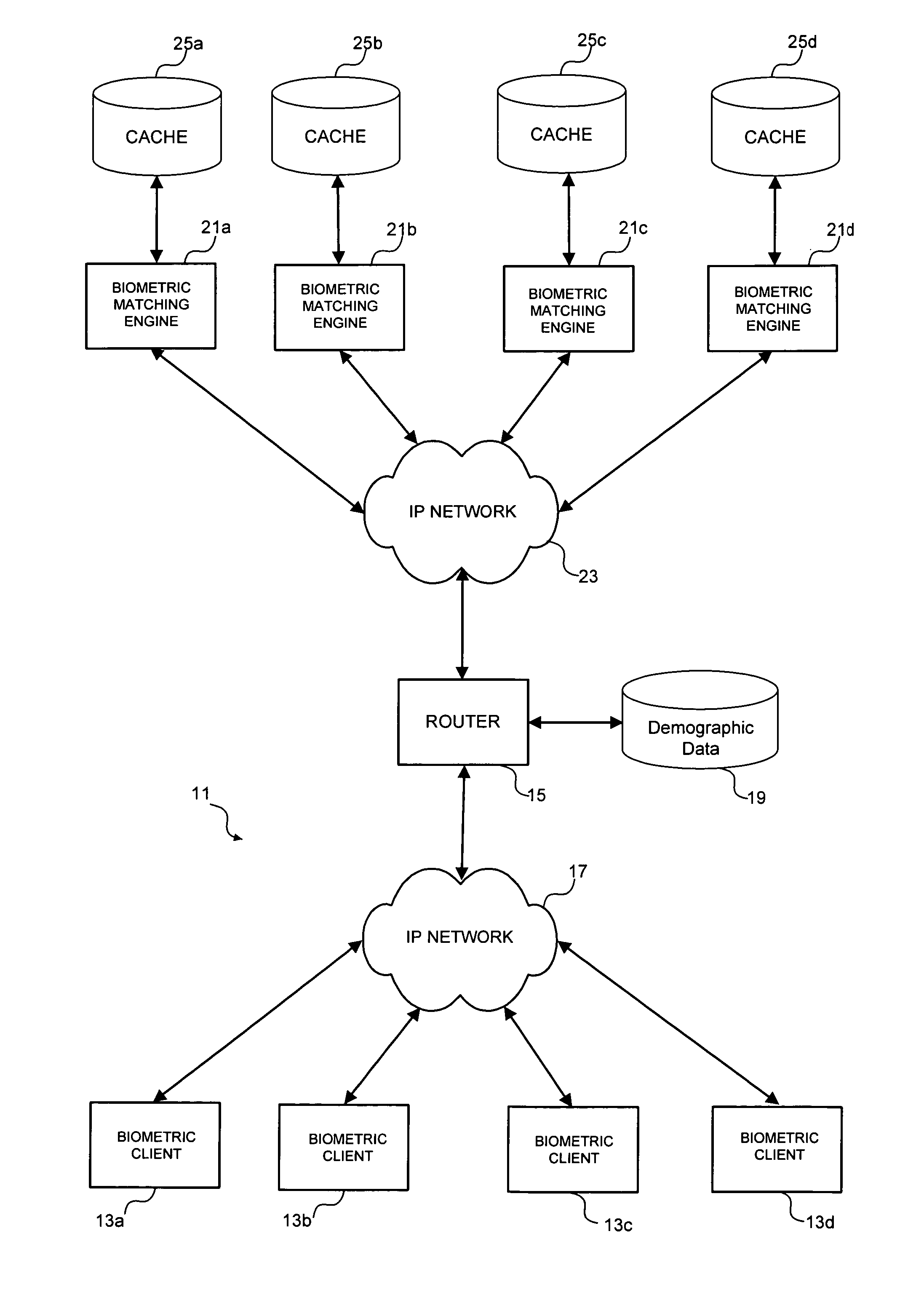
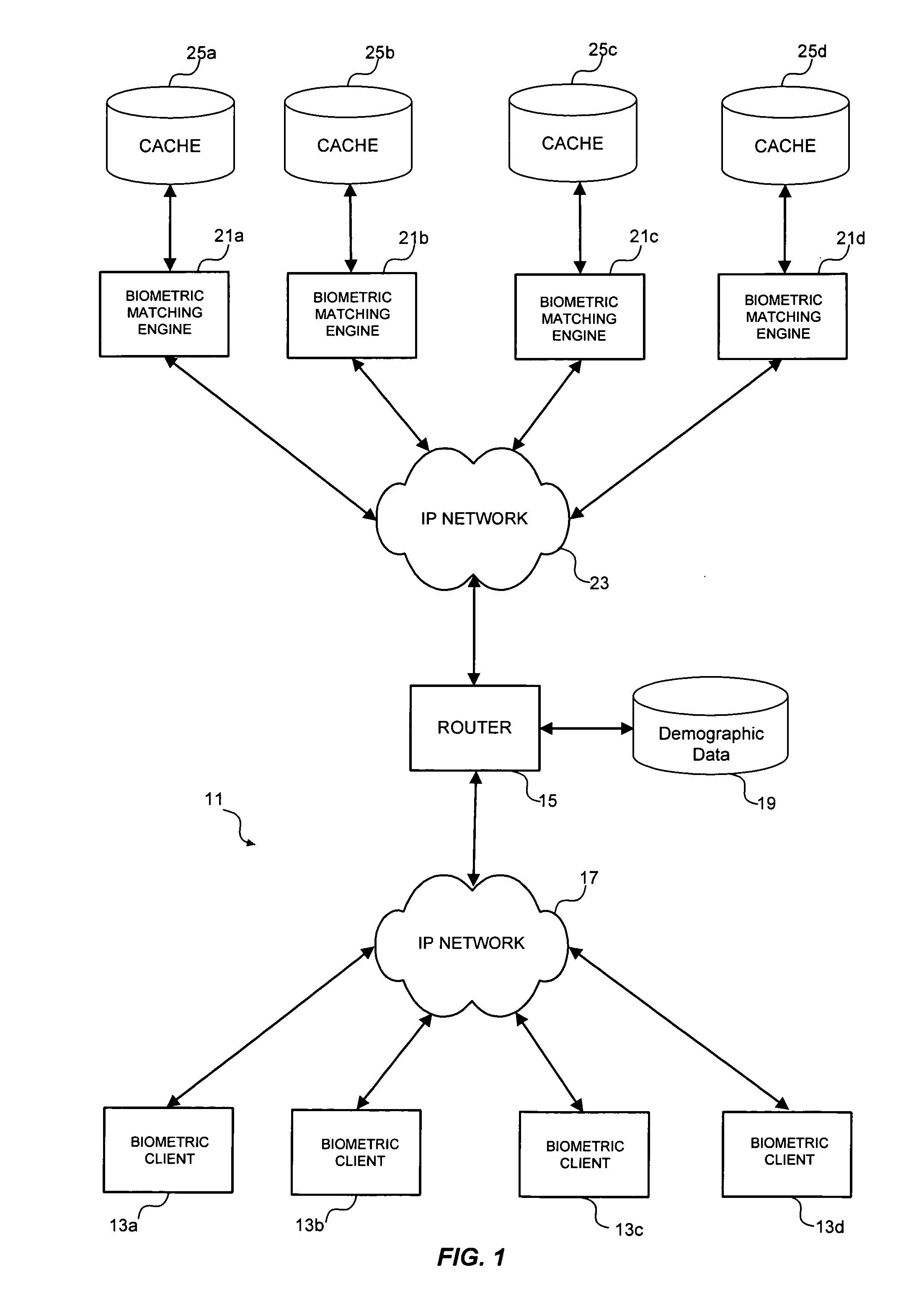
[0029] Referring now to the drawings, and first to FIG. 1, an embodiment of a system according to the present invention is designated generally by the numeral 11. System 11 includes a plurality of biometric clients 13. Biometric clients 13 comprise computers having installed thereon a suitable operating system and biometric software, preferably implemented in a client software development kit (SDK).

[0030] Biometric clients 13 are in communication with a router 15 through a suitable network, such as Internet Protocol (IP) network 17. Router 15 comprises a computer having installed thereon a suitable operating system and biometric software programmed according to the present invention. Router has associated therewith storage 19 for storing demographic data.

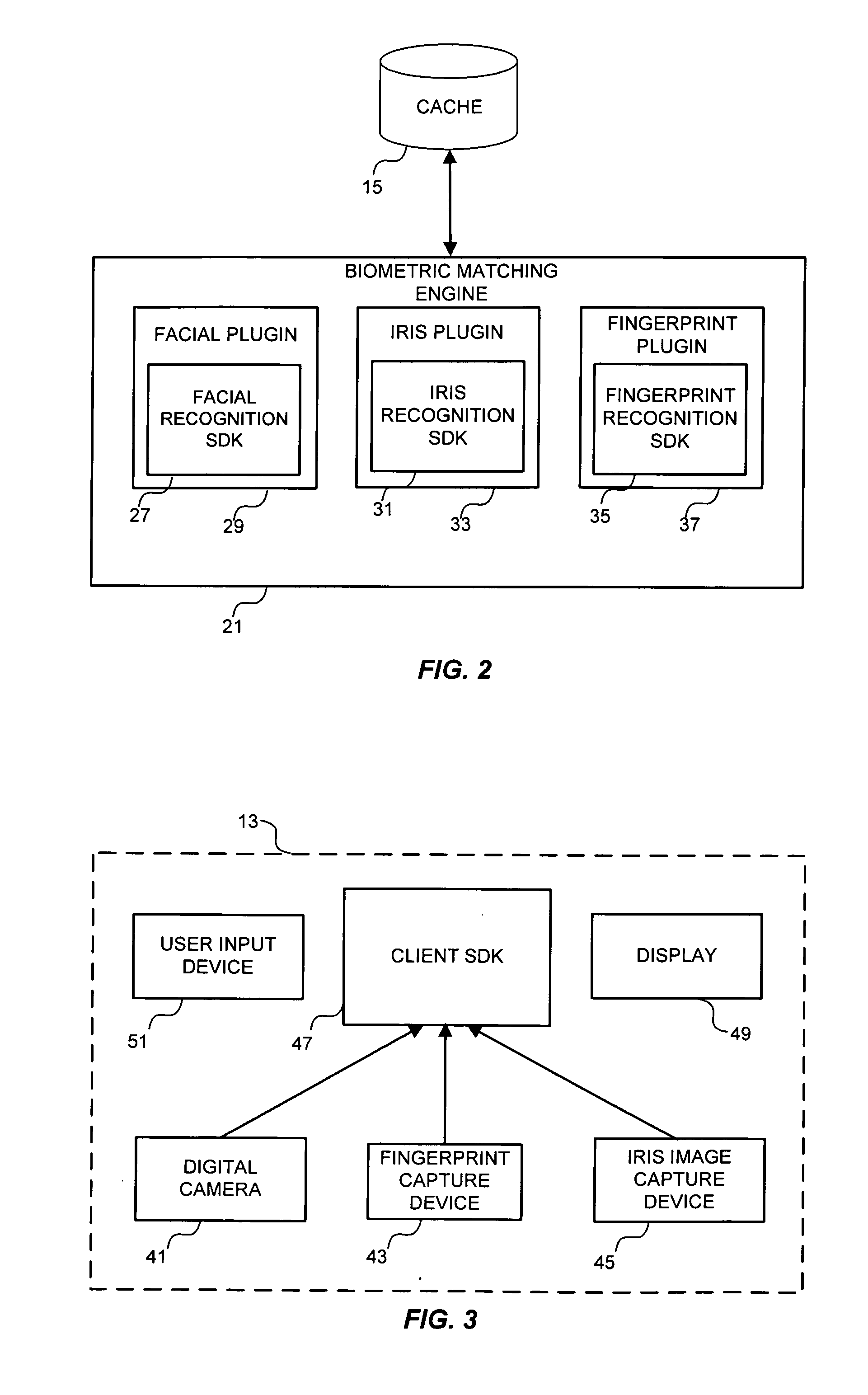
[0031] Router 15 is in communication with a plurality of biometric matching engines 21 through a suitable network, such as IP network 23. Each biometric matching engine 21 comprises a computer having installed thereon a suitable o...


PUM


Abstract

A multimodal biometric identification or authentication system includes a plurality of biometric clients. Each of the biometric clients may include devices for capturing biometric images of a plurality of types. The system includes a router in communication with the biometric clients. The router receives biometric images from, and returns biometric scores or results to, the biometric clients. The system includes a plurality of biometric matching engines in communication with the router. Each biometric matching engine includes multiple biometric processors. Each biometric processor is adapted to process biometric data of a particular type. The biometric matching engines transmit and receive biometric data to and from the router.

Description

BACKGROUND OF THE INVENTION [0001] The present invention relates generally the field of biometric identification and authentication, and more particularly to a multimodal biometric system and method. [0002] Biometrics is a generic term for characteristics that can be used to distinguish one individual from another, particularly through the use of digital equipment. An example of a biometric is a fingerprint. Trained analysts have long been able to match fingerprints in order to identify individuals. More recently, computer systems have been developed to match fingerprints automatically. Examples of biometrics that have been, or are now being, used to identify, or authenticate the identity of, individuals include 2D face, 3D face, hand geometry, single fingerprint, ten finger live scan, iris, palm, full hand, signature, ear, finger vein, retina, DNA and voice. Other biometric may include characteristic gaits, lip movements and the like. New biometric are being developed or discovered...

Claims


Application Information

Patent Timeline
Patent Type & Authority Applications(United States)
IPC IPC(8): G06K9/00
CPCG06K9/00885G06K9/00979G06V40/10G06V10/95
Inventor MILLER, S. JAMES JR.WILLIS, WILLIAM FREDERICLAU, JOHANN H.DLAB, DANIEL
Owner IMAGEWARE SYST
Why Eureka
Try Eureka