Methods and apparatus for treating spinal stenosis

a spinal stenosis and spinal canal technology, applied in the field of spinal surgery, can solve the problems of increasing causing pain or numbness in the legs, so as to facilitate spinal flexion, and reduce the risk of laminectomy.

Inactive Publication Date: 2006-05-18
NUVASIVE
View PDF99 Cites 647 Cited by
  • Summary
  • Abstract
  • Description
  • Claims
  • Application Information

AI Technical Summary

Benefits of technology

[0251] This invention is directed to surgical apparatus for treating spinal stenosis, without the need for laminectomy. Broadly the invention resides in a device configured for placement posteriorly to a spinal canal between vertebral bodies to distract the spine and enlarge the spinal canal. In the preferred embodiments the device permits spinal flexion while limiting spinal extension, thereby providing an effective treatment for treating spinal stenosis. The invention may be used in the cervical, thoracic, or lumbar spine.

Problems solved by technology

Pressure on the lower part of the spinal cord, or on nerve roots branching out from that area, may give rise to pain or numbness in the legs.
Surgeons risk injuring the nerves or the spinal cord as they enlarge the spinal canal.
In addition, elderly patients frequently have co-morbidities that increase the risk of laminectomy.
Complications of laminectomy include increased back pain, infection, nerve injury, blood clots, paralysis, prolonged recovery, and death.
Current fusion techniques require abrasion of large surfaces of bone.
Current fusion techniques increase the risk of spinal stenosis procedures.
Fusion also prolongs patient recovery following spinal stenosis surgery.

Method used


Image

  • Methods and apparatus for treating spinal stenosis
  • Methods and apparatus for treating spinal stenosis
  • Methods and apparatus for treating spinal stenosis

Examples


Embodiment Construction

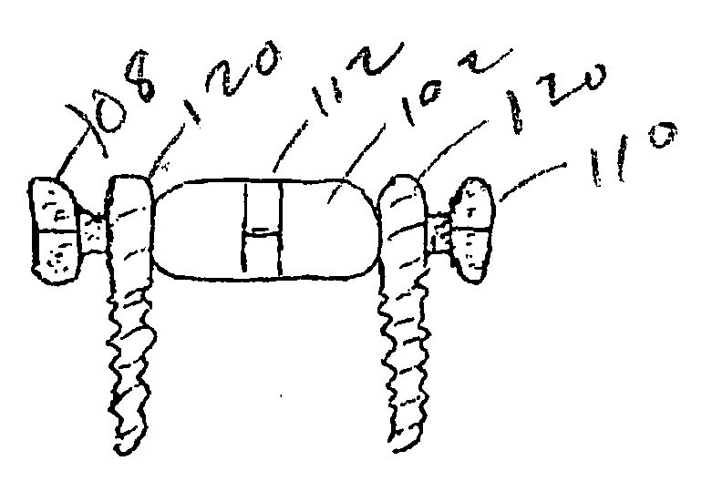
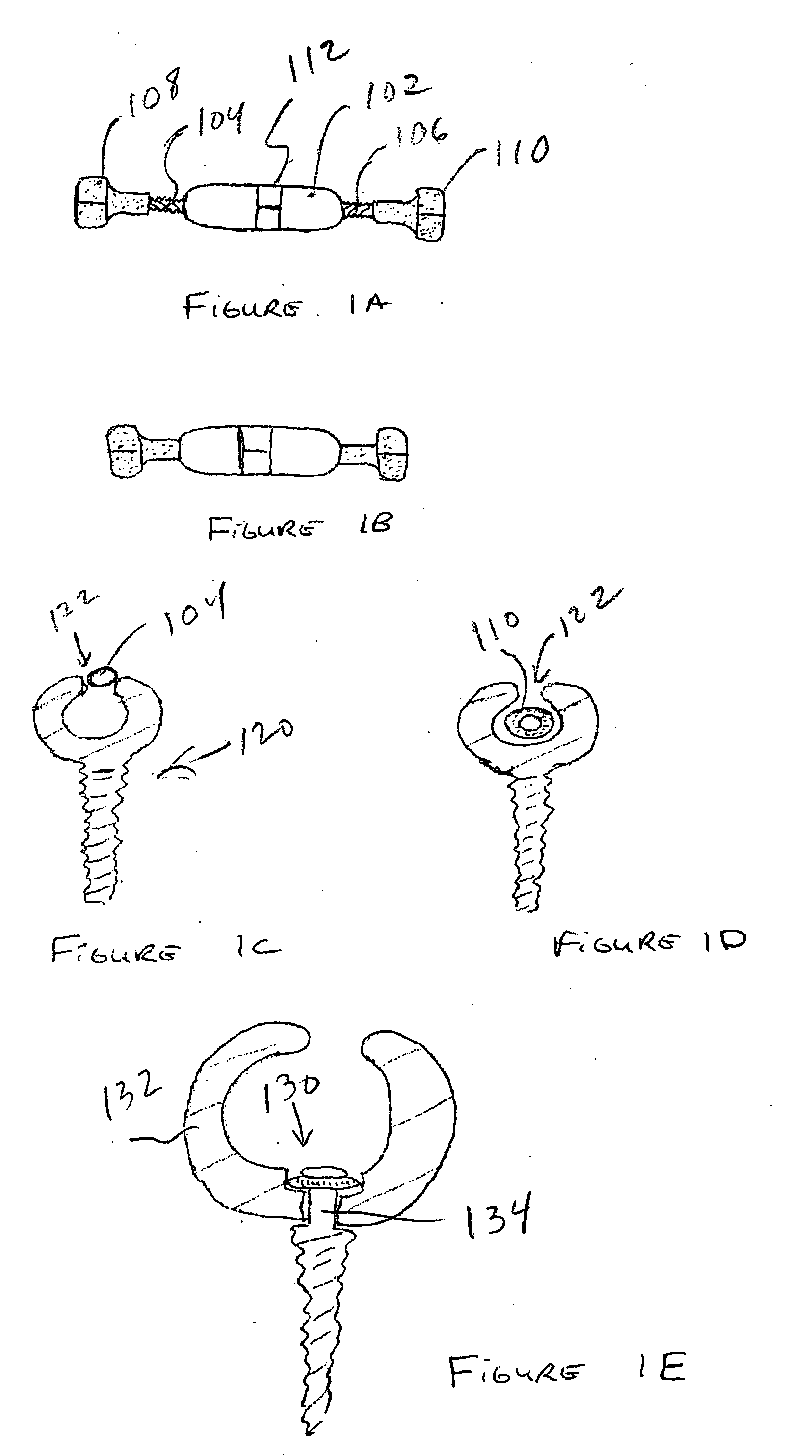
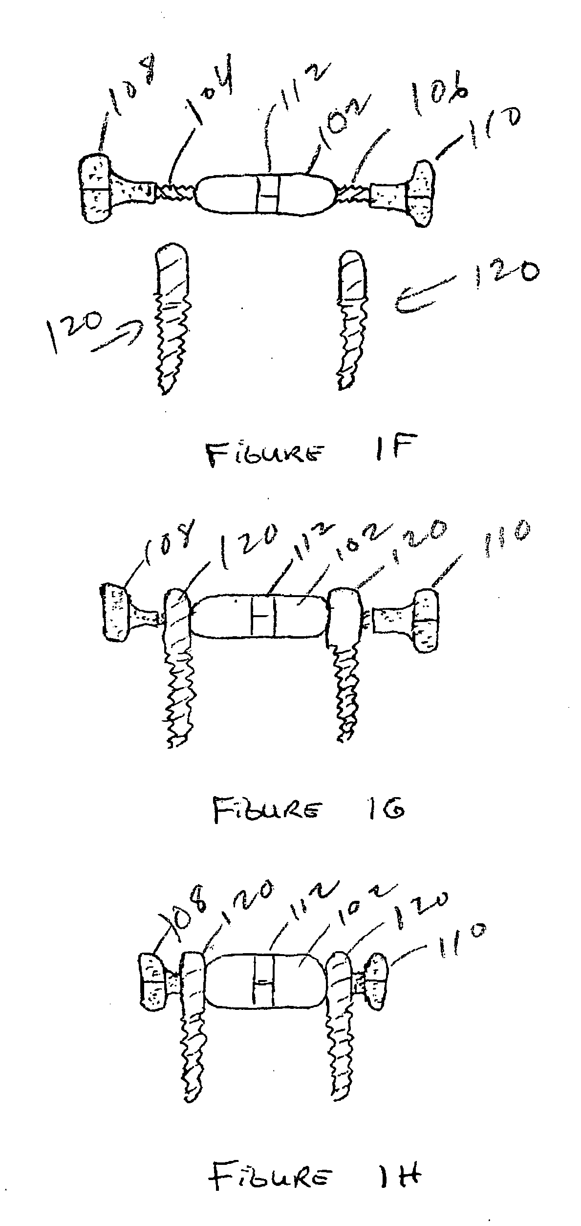
[0258]FIG. 1A is a lateral view of a three-component device used to treat spinal stenosis, drawn in its extended position. The central rod component 102 is threaded 104, 106 on both ends. One end of the component has left-handed threads. The other end of the rod component has right-handed threads. Bolt-like components 108, 110 are threaded onto the ends of the rod component. As discussed in further detail below, the rod component is coupled to pedicle screws then adjusted to force the screws apart. This permits spinal flexion, but limits spinal extension, thereby distracting the spine and enlarging the spinal canal.

[0259]FIG. 1B is a lateral view of the device of FIG. 1A drawn in its contracted position. Tools are used to prevent rotation of the end components. A wrench may be used to rotate the rod component placed on flats 112. Rotating the rod component, while preventing rotation of the end components, causes the end components to advance along the treaded portions of the rod, s...


PUM


Abstract

Surgical implants are configured for placement posteriorly to a spinal canal between vertebral bodies to distract the spine and enlarge the spinal canal. In the preferred embodiments the device permits spinal flexion while limiting spinal extension, thereby providing an effective treatment for treating spinal stenosis without the need for laminectomy. The invention may be used in the cervical, thoracic, or lumbar spine. Numerous embodiments are disclosed, including elongated, length-adjustable components coupled to adjacent vertebral bodies using pedicle screws. The preferred embodiments, however, teach a device configured for placement between adjacent vertebral bodies and adapted to fuse to the lamina, facet, spinous process or other posterior elements of a single vertebra. Various mechanisms, including shape, porosity, tethers, and bone-growth promoting substances may be used to enhance fusion. The tether may be a wire, cable, suture, or other single or multi-filament member. Preferably, the device forms a pseudo-joint in conjunction with the non-fused vertebra. Alternatively, the device could be fused to the caudal vertebra or both the cranial and caudal vertebrae.

Description

REFERENCE TO RELATED APPLICATION [0001] This application claims priority from U.S. Provisional Application Ser. No. 60 / 629,018, filed Nov. 18, 2004, the entire content of which is incorporated herein by reference.FIELD OF THE INVENTION [0002] This invention relates generally to spine surgery and, in particular, to methods and apparatus for treating spinal stenosis. BACKGROUND OF THE INVENTION [0003] Spinal stenosis is a narrowing of spaces in the spine, results in pressure on the spinal cord and / or nerve roots. This disorder usually involves the narrowing of one or more of the following: (1) the canal in the center of the vertebral column through which the spinal cord and nerve roots run, (2) the canals at the base or roots of nerves branching out from the spinal cord, or (3) the openings between vertebrae through which nerves leave the spine and go to other parts of the body. [0004] Pressure on the lower part of the spinal cord, or on nerve roots branching out from that area, may g...

Claims


Application Information

Patent Timeline
Patent Type & Authority Applications(United States)
IPC IPC(8): A61F2/30
CPCA61B17/7004A61B17/7005A61B17/7008A61B17/7014A61B17/7023A61B17/7032A61B17/7053A61B17/7062A61B17/7064A61B17/7067A61B17/025A61B17/7068A61B2017/0256A61B2017/681A61F2/4455
Inventor FERREE, BRET A.TOMPKINS, DAVID
Owner NUVASIVE
Why Eureka
Try Eureka