Improved dust collection for panel saw

a technology for panel saws and dust collection, applied in the field of panel saws, can solve the problems of large amount of sawdust created and dispersed, lack of adequate solutions or solutions, and the number of problems and shortcomings of the panel saw, and achieve the effect of improving dust collection efficiency and user safety

Inactive Publication Date: 2006-05-25
POWELL MICHAEL S
View PDF14 Cites 3 Cited by
  • Summary
  • Abstract
  • Description
  • Claims
  • Application Information

AI Technical Summary

Benefits of technology

[0011] The present invention overcomes the disadvantages and shortcomings in the art by adapting a vertical cut panel saw to vastly improve dust collection efficiency and user safety. In accordance with the present invention a panel saw is adapted with an improved protective blade cover having an oversized duct connected to a vacuum-type dust collection apparatus by a hose. The blade cover duct has an angled end configured to deflect and direct sawdust and wood chips downstream into the dust collection hose. A device that functions as both a guide and pulley is mounted to the top of the panel saw frame to allow the dust collection vacuum hose to travel over the frame in trailing relation with the carriage carrying the rotary power saw. The rotary power saw carriage is further adapted with a skirt attached in surrounding relation with the projecting saw blade and projecting therefrom in sweeping contact that defines a sawdust containment volume between the workpiece to be cut and the underside of the rotary saw power carriage. The panel saw frame is further adapted with a generally U-shaped sawdust trough connected thereto and disposed in vertical aligned relation with the cutting channel defined by the panel saw frame so as to contain any sawdust projected behind the workpiece. A T-shaped fitting connected to the bottom of the vertically disposed sawdust trough and functions as a catch basin for sawdust ejected into the trough. The T-shaped fitting includes a rearwardly projecting leg adapted for connection to a dust collection vacuum hose thereby providing the panel saw with a second dust collection connection.
[0016] Still another object of the present invention is to provide components for installation to a conventional panel saw to vastly improve sawdust containment and collection.

Problems solved by technology

While the panel saw provide an efficient and proven power tool for cutting panels and sheets of plywood, there remain a number of problems and shortcomings associated with the operation thereof that heretofore have not been adequately solved or addressed.
One such problem associated with certain panel saws relates to the substantial amount of sawdust created and dispersed when cutting.
While this problem has been widely recognized for many years, panel saw manufactures and others have failed to develop an effective dust collection system for use with these saws.
One common, yet ineffective, solution has been to provide the saw blade with a protective guard or hood adapted with a suction port connected to a vacuum-generating dust collection system by a hose.
Such attempts, however, have proven unsatisfactory and generally ineffective.
Striebig's reliance, however, on complex spindles and slidable exhaust ducts has not gained widespread acceptance.
In addition, advances in the art of panel saw dust collection have not proven successful in substantially containing and collecting sawdust generated by the panel saw.

Method used


Image

  • Improved dust collection for panel saw
  • Improved dust collection for panel saw
  • Improved dust collection for panel saw

Examples


Embodiment Construction

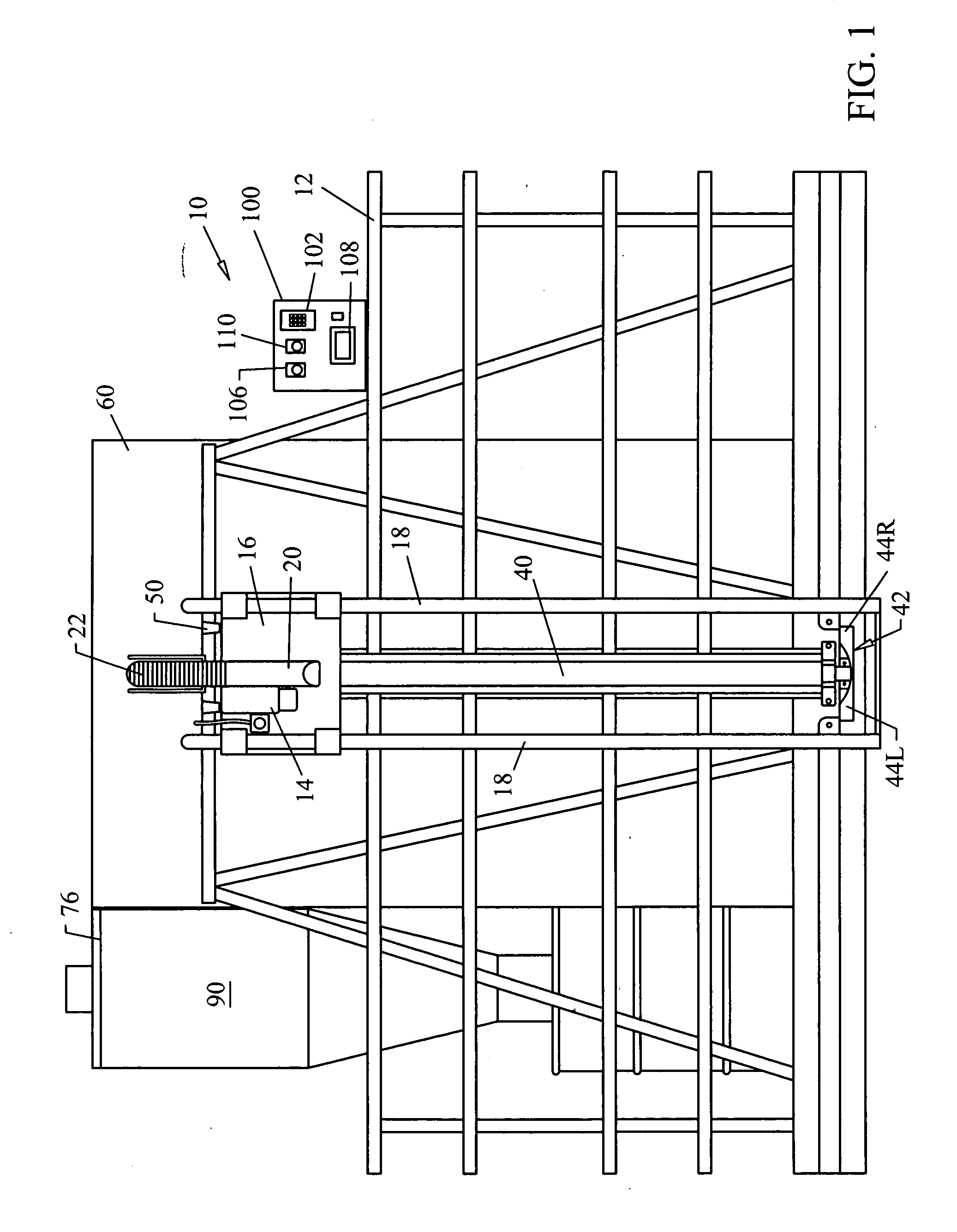
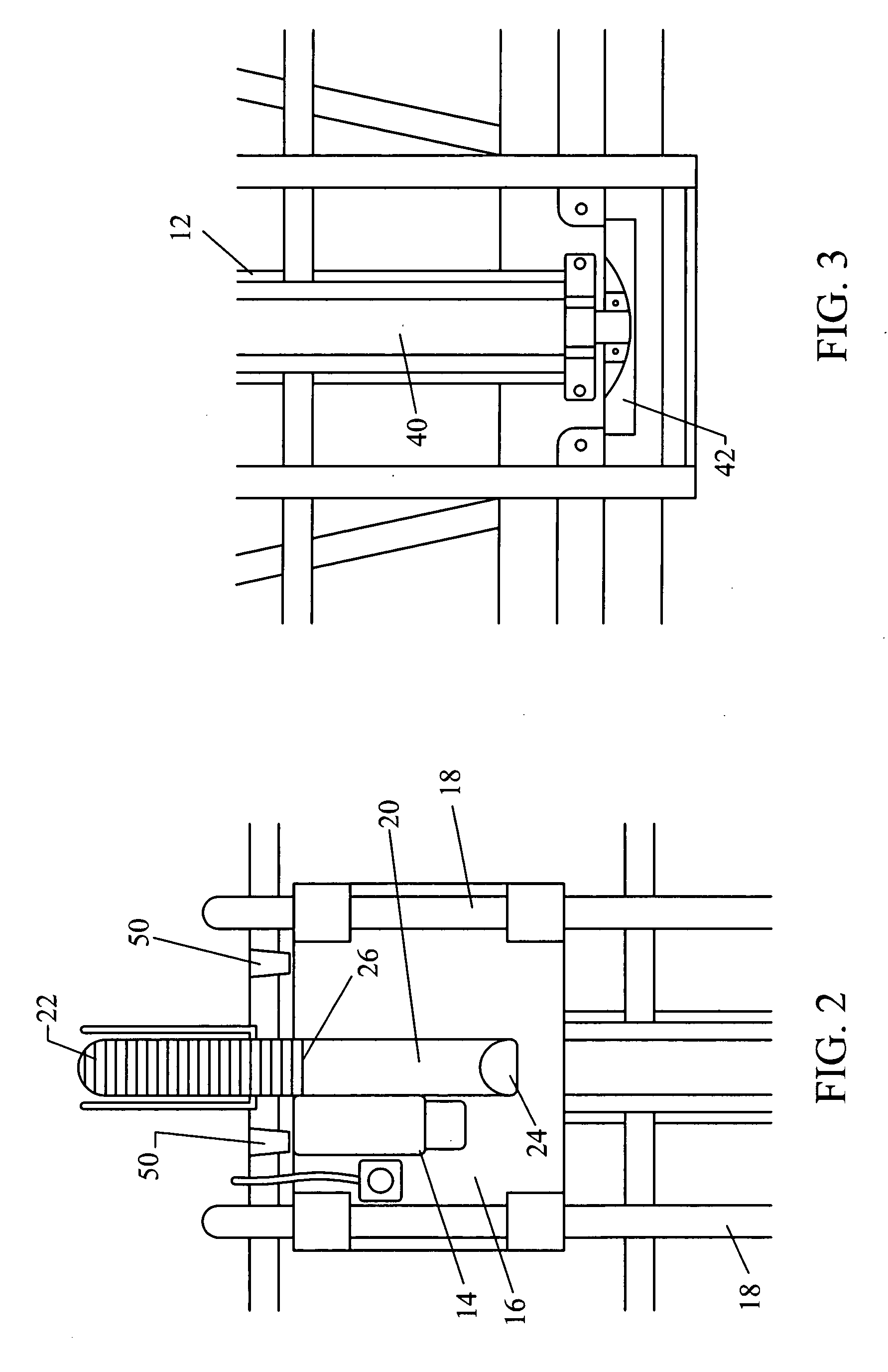
[0027] With reference now to the drawings, FIGS. 1-7, depict a panel saw, generally referenced as 10, adapted for improved safety and dust collection in accordance with the present invention. Panel saw 10 includes a frame 12 disposed in a generally angled vertical configuration for providing a supporting structure for panels, such as plywood, to be cut. Frame 12 further includes a rotary power saw 14 mounted on a carriage 16 configured for vertical travel along a pair of laterally spaced tubular guides 18. Carriage 16 is typically provided with a pulley and counterweight to negate gravitational force, and in most models the force applied by the counterweight exceeds that of the saw carriage so as to bias the carriage to the uppermost configuration. Accordingly, panels supported by frame 12 are cut by the power saw as carriage 16 travels downward along guides 18 from the uppermost position depicted in FIG. 1. It is noted that each of the above-referenced structures are found in panel...


PUM

PropertyMeasurementUnit
volumeaaaaaaaaaa
lengthaaaaaaaaaa
timeaaaaaaaaaa

Abstract

A panel saw is adapted with an improved dust collection system including a protective blade cover having an oversized duct connected to a vacuum-type dust collection apparatus by a hose. The blade cover duct has an angled end configured to deflect and direct sawdust and wood chips downstream into the dust collection hose. A device that functions as both a guide and pulley is mounted to the top of the panel saw frame to allow the dust collection vacuum hose to travel over the frame in trailing relation with the carriage carrying the rotary power saw. The rotary power saw carriage is further adapted with a skirt attached in surrounding relation with the projecting saw blade and projecting therefrom in sweeping contact that defines a sawdust containment volume between the workpiece to be cut and the underside of the rotary saw power carriage. The panel saw frame is further adapted with a generally U-shaped sawdust channel connected thereto and disposed in vertical aligned relation with the saw blade so as to contain any sawdust projected behind the workpiece. A sawdust cup is connected to the bottom of the vertically disposed sawdust channel and functions as a catch basin for sawdust ejected into the channel. The sawdust cup includes a rearwardly projecting leg adapted for connection to a dust collection vacuum hose thereby providing the panel saw with a second dust collection connection.

Description

CROSS REFERENCE TO RELATED APPLICATIONS [0001] N / A STATEMENT REGARDING FEDERALLY SPONSORED RESEARCH OR DEVELOPMENT [0002] N / A COPYRIGHT NOTICE [0003] A portion of the disclosure of this patent document contains material that is subject to copyright protection. The copyright owner has no objection to the facsimile reproduction by anyone of the patent document or patent disclosure as it appears in the Patent and Trademark Office patent file or records, but otherwise reserves all copyrights rights whatsoever. BACKGROUND OF THE INVENTION [0004] 1. Field of the Invention [0005] The present invention relates to panel saws, and more particularly to improvements in panel saws that provide vastly improved dust collection. [0006] 2. Description of Related Art [0007] A panel saw is a power saw apparatus specifically designed to cut relatively large and thin panels of material, such as plywood. Typical panel saws include a generally vertical angled frame having a front side adapted to receive a...

Claims


Application Information

Patent Timeline
Patent Type & Authority Applications(United States)
IPC IPC(8): B26D7/06
CPCB23D59/006B27B5/07Y10T83/207Y10T83/7763
Inventor POWELL, MICHAEL
Owner POWELL MICHAEL S
Why Eureka
Try Eureka