Eureka AIR delivers breakthrough ideas for toughest innovation challenges, trusted by R&D personnel around the world.

Rotor brake mechanism for curtain linkage system

Inactive Publication Date: 2006-05-25
HUANG SHIEN TE
View PDF5 Cites 26 Cited by
  • Summary
  • Abstract
  • Description
  • Claims
  • Application Information

AI Technical Summary

Benefits of technology

[0012] Because the front and rear ends of three rollers are movably disposed in the aforementioned slide grooves, thus two points from such can thus determine a straight line relation, and be utilized to receive uniform acting forces which effectuate smooth sliding, thereby allowing shortening in length of the rollers, which correspondingly reduces thickness of entire brake mechanism.
[0013] Utilizing the three rollers and the three blocking rods, optimum average component load on a circular plane is attained, thereby acquiring unhindered and unequivocal operating and braking action.
[0014] After assemblage, the brake mechanism forms a functional entity configured as a single body, which thereby facilitates post-production assembly.
[0016] Regarding manufacturing methods of each component, apart from the shafts, all other components can each be formed from a single punch by adopting a punching method, and assembled by employing tolerance crimping assembly. Manufacture working procedure is extremely simple, convenient and fast.

Problems solved by technology

Utilizing the three rollers and the three blocking rods, optimum average component load on a circular plane is attained, thereby acquiring unhindered and unequivocal operating and braking action.

Method used


Image

  • Rotor brake mechanism for curtain linkage system
  • Rotor brake mechanism for curtain linkage system
  • Rotor brake mechanism for curtain linkage system

Examples


Embodiment Construction

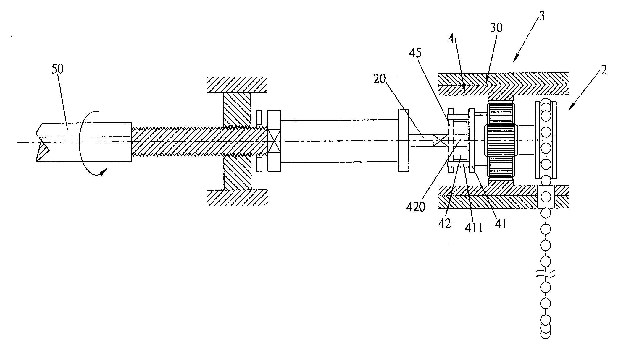
[0026] Referring to FIG. 3, which shows a detailed configuration according to the present invention, and which primarily comprises a drive unit 2. A converter device 3 can be inter-disposed between the drive unit 2 and a brake mechanism 4 according to needs of velocity torsion, and which transmits appropriate motive power to the brake mechanism 4 therewith.

[0027] The motive power of the drive unit 2 is directly transmitted to a turntable 41 of the brake mechanism 4, which realizes direct actuation of the turntable 41 thereof. Blocking rods 411 are disposed on the turntable 41, and configured so as to inwardly face therefrom, wherewith checking motion of a rotor 42 is effectuated. The drive unit 2 and the brake mechanism 4 are embodied in a housing 30 thereby forming a single body.

[0028] A shaped orifice 420 is defined in the rotor 42, and which provides for a linkage system shaft 20 to connect thereinto. Accordingly, the motive power of the drive unit 2 is transmitted to an angula...


PUM


Abstract

A rotor brake mechanism for curtain linkage system, wherein a reverse acting force brake mechanism is indirectly produced between a drive unit and a roll-up and release mechanism. The rotor brake mechanism primarily utilizes a turntable, whereon three blocking rods are separately disposed and three slide grooves are separately defined so as to be equi-angularly spaced on the turntable thereof. The slide grooves provide for movably disposing of rollers therein. A triangular rotor is movable disposed within the rotor brake mechanism. The turntable and a combinatory member are clamped as a pair on front and rear end openings of a limit ring respectively. Utilizing the correspondingly configured slide grooves, two points from such can thus determine a straight line relation, and utilizing the three blocking rods, three points can determine a plane, thereby uniformly distributing acting forces and effectuating unhindered operation therefrom.

Description

BACKGROUND OF THE INVENTION [0001] (a) Field of the Invention [0002] The present invention relates to a rotor brake mechanism for curtain linkage system, more particularly to a curtain linkage system, wherein a reverse acting force brake mechanism is indirectly produced between a drive unit and a roll-up and release mechanism. [0003] (b) Description of the Prior Art [0004] Regarding a brake mechanism of a curtain linkage system, reasons for necessity of such a brake configuration are that during course of releasing curtain slats or at a time of implementing opening of the curtain slats, the slats can be subject to external force effects of airflow, wind pressure, and so on, whereupon reverse transmission to a drive unit results, which causes deformation in anti-dazzling surfaces of the slats or deviation in angle of anti-dazzle (see FIG. 1). [0005] The curtain set 5 primarily comprises a top rail 51 with slats 53 configured below, and the top rail 51 is connected to a bottom rail 54...

Claims


Application Information

Patent Timeline
IPC IPC(8): E06B9/307
CPCE06B9/307E06B9/322E06B2009/285
Inventor HUANG, SHIEN-TE
Owner HUANG SHIEN TE
Why Eureka
Eureka Blog
Learn More