Method and apparatus for cooling flasked instrument assembles

a technology of instrument assembly and cooling method, which is applied in the direction of insulation, well accessories, borehole/well accessories, etc., can solve the problems of inability to extract hot electronic components, inability to cool downhole instrument assembly by radiation and convection alone, and inability to cool down logging tools. the effect of moisture damage to the electronic components

Inactive Publication Date: 2006-05-25
HALLIBURTON ENERGY SERVICES INC
View PDF18 Cites 10 Cited by
  • Summary
  • Abstract
  • Description
  • Claims
  • Application Information

AI Technical Summary

Benefits of technology

[0007] The present invention is directed to apparatus for use in a downhole assembly comprising a chamber containing thermally sensitive instrumentation and at least one passage through the chamber through which cooling fluid may flow. The thermally sensitive instrumentation may comprise electronic, optical or mechanical components. In one specific embodiment, apparatus in accordance with the present invention comprises a thermal flask in which an electronic chassis resides that contains electronic components that are used in a downhole instrument assembly. A thermal flask according to the present invention includes a passage through the flask proximate the electronic chassis. The passage has an inlet and an outlet, and the inlet is adapted to be coupled to a source of fluid. As the fluid in the fluid source flows in the passage, active cooling of the electronics chassis in the thermal flask assembly is provided. The passage is hermetically sealed from the volume containing the electronic components to prevent moisture damage to the electronic components.

Problems solved by technology

It is well-known that downhole instrument assemblies are used in extremely hostile environments.
Downhole instrument assemblies typically comprise thermally sensitive components which have a maximum temperature above which they will not operate properly.
Accordingly, research studies by the Assignee of this application have shown that cooling a logging tool by radiation and convection alone (i.e., passive cooling) will require a substantial amount of time, e.g., sixty plus hours, before logging operations may be resumed.
Further, it is not feasible to extract the hot electronic components from the thermal flask in an effort to expedite cooling, because such extraction subjects the electronic components to thermal shock and exposure to atmospheric moisture.

Method used


Image

  • Method and apparatus for cooling flasked instrument assembles
  • Method and apparatus for cooling flasked instrument assembles
  • Method and apparatus for cooling flasked instrument assembles

Examples


Embodiment Construction

[0017] It will be appreciated that the present invention may take many forms and embodiments. Some embodiments of the present invention are described so as to give an understanding of the invention. Thus, the embodiments of the invention that are described herein are intended to be illustrative and not limiting of the invention.

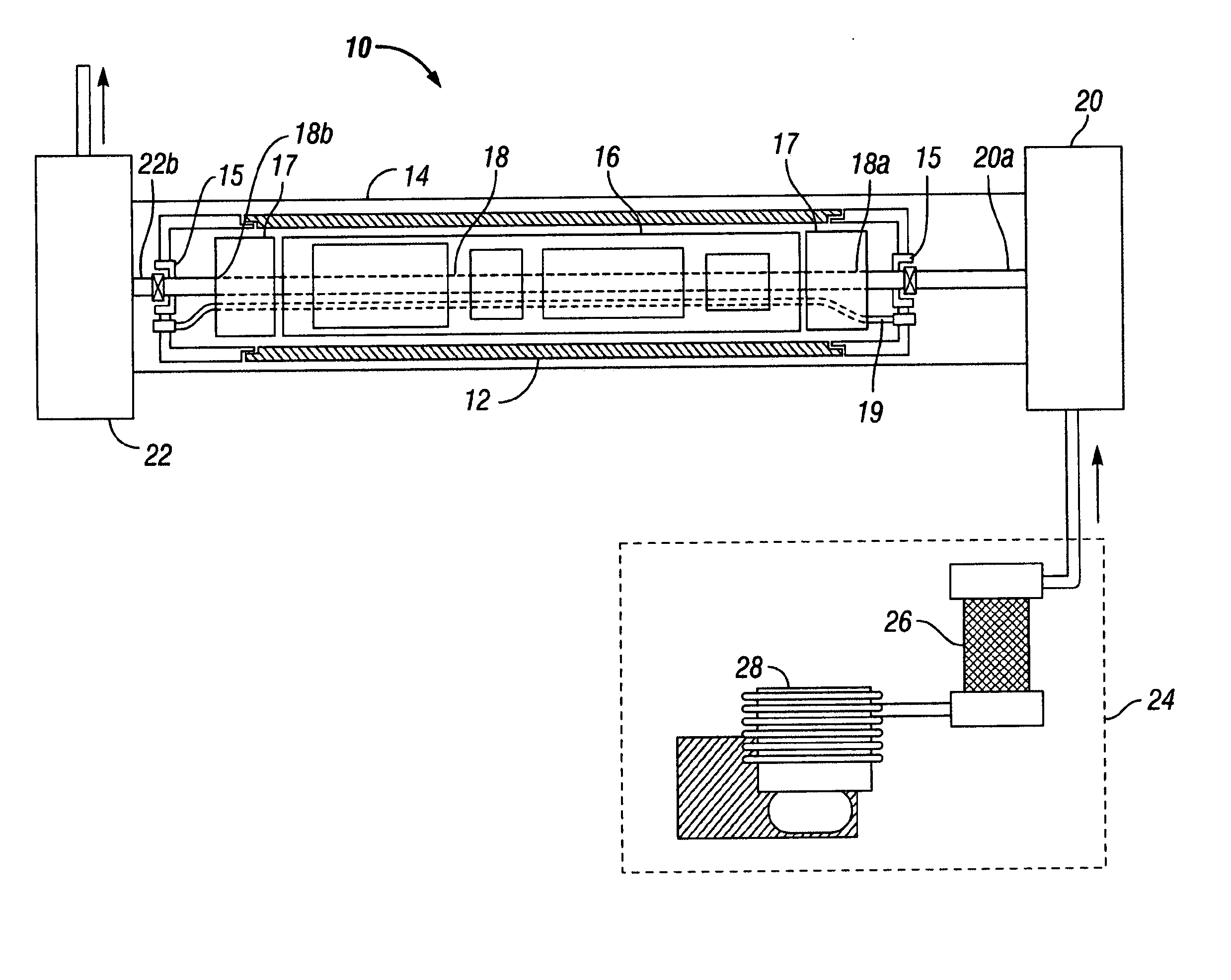
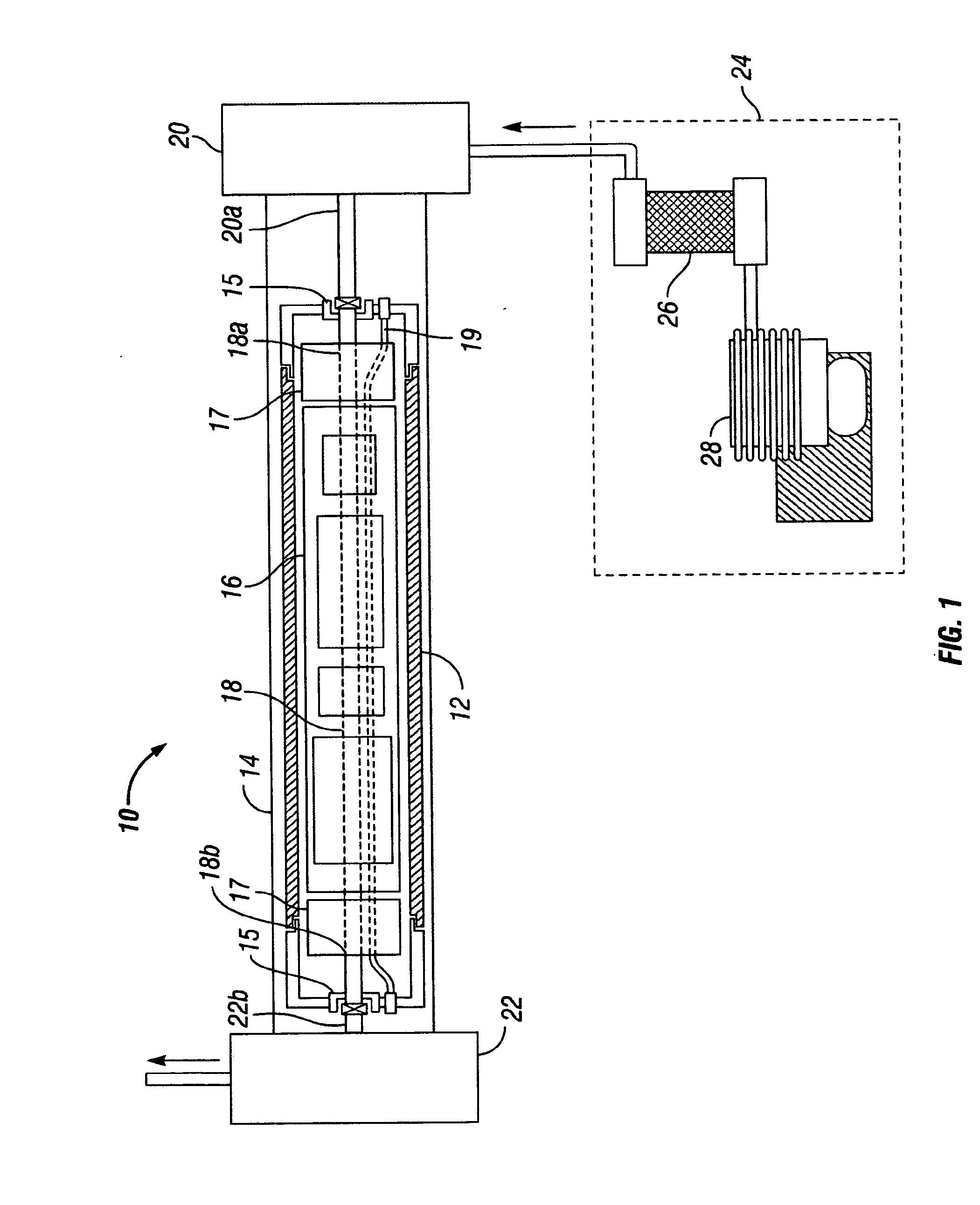
[0018] As used in this specification and in the appended claims, two items are “operatively connected” when those items are directly connected to one another or connected to one another via another element. Additionally, the term “downhole instrument assembly” is used to refer to any instrument which is used in a downhole environment and which contains components which only operate satisfactorily up to a specified temperature limit. A “downhole instrument assembly” may, for example, comprise an electronic chassis which is encased in a thermal flask, and examples of such assembles are found in logging tools, logging while drilling tools, measurement while dri...


PUM


Abstract

Method and apparatus are provided to accelerate the cooling of thermally sensitive components in a chamber of a downhole instrument assembly. In accordance with the invention, a passage is formed in the chamber and a fluid is conveyed through the passage to cool the components to the desired temperature. By using the method and apparatus of the present invention the amount of time to cool the components is dramatically less than the time required for cooling using conventional techniques.

Description

BACKGROUND OF THE INVENTION [0001] 1. Field of the Invention [0002] The present invention relates to flasked instrument assemblies that are used in downhole tools, and, in particular, to the cooling of the electronic chassis in such an assembly. [0003] 2. Description of the Prior Art [0004] It is well-known that downhole instrument assemblies are used in extremely hostile environments. Downhole tools such as logging tools, logging while drilling tools, measurement while drilling tools, and guidance tools that are used in the drilling of deviated wells employ such assemblies. Downhole instrument assemblies typically comprise thermally sensitive components which have a maximum temperature above which they will not operate properly. Such components may, for example, be electronic, optical or mechanical devices which are used to measure various parameters of the well or the formation or the fluid in the well or the fluid in the formation. In order to protect the components in these down...

Claims


Application Information

Patent Timeline
Patent Type & Authority Applications(United States)
IPC IPC(8): E21B36/00
CPCE21B47/011E21B47/017E21B47/0175
Inventor MORYS, MARIAN L.MURTA, SCOTT P.EPSTEIN, ROBERT E.
Owner HALLIBURTON ENERGY SERVICES INC
Why Eureka
Try Eureka