Freefall windlass with governor

a windlass and governor technology, applied in the field of windlasses, can solve the problems of restricting the rotational speed of the spool gear, the provided governing gear is not sufficient to override the motor,

Inactive Publication Date:
View PDF7 Cites 11 Cited by
  • Summary
  • Abstract
  • Description
  • Claims
  • Application Information

AI Technical Summary

Benefits of technology

[0008] In addition to the basic components mentioned, the windlass of the present invention includes a governing gear that remains in meshed relationship with the spool gear at all times but a spring biased resistance design allows the governing gear to restrict rotation of the spool gear to a desired speed. The resistance provided by the governing gear is not sufficient to override the motor when the windlass is in a retrieving mode but does restrict rotational speed of the spool gear when the anchor on the anchor cable is in a freefall or payout mode.

Problems solved by technology

The resistance provided by the governing gear is not sufficient to override the motor when the windlass is in a retrieving mode but does restrict rotational speed of the spool gear when the anchor on the anchor cable is in a freefall or payout mode.

Method used


Image

  • Freefall windlass with governor
  • Freefall windlass with governor
  • Freefall windlass with governor

Examples


Embodiment Construction

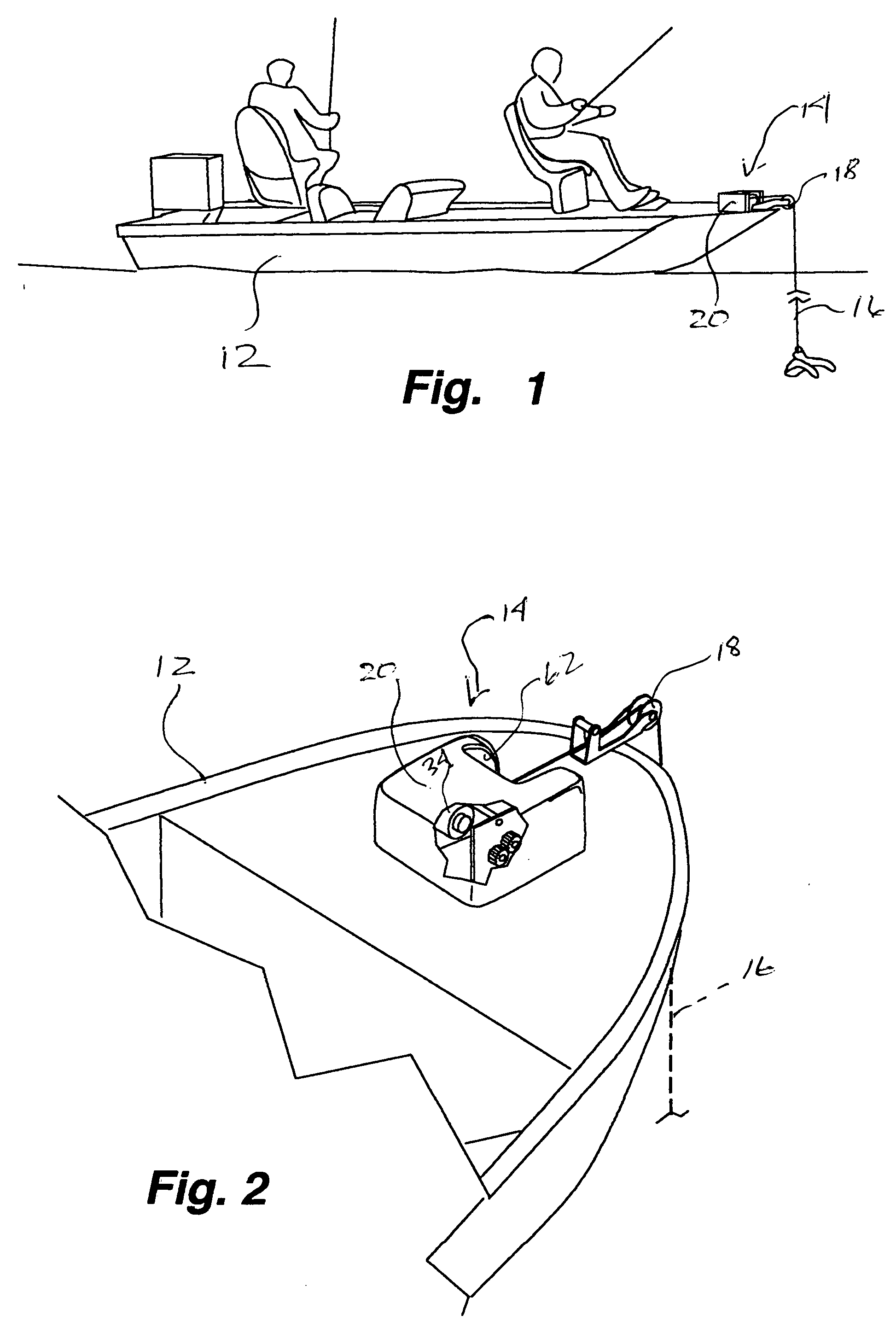
[0021] With reference first to FIGS. 1 and 2, a boat 12 illustrated as a small fishing vessel includes a windlass 14 in accordance with the present invention mounted on the bow of the boat so that the anchor cable 16 emanating from the windlass can pass over a guide pulley 18 allowing the anchor to remain spaced from the boat in a conventional manner.

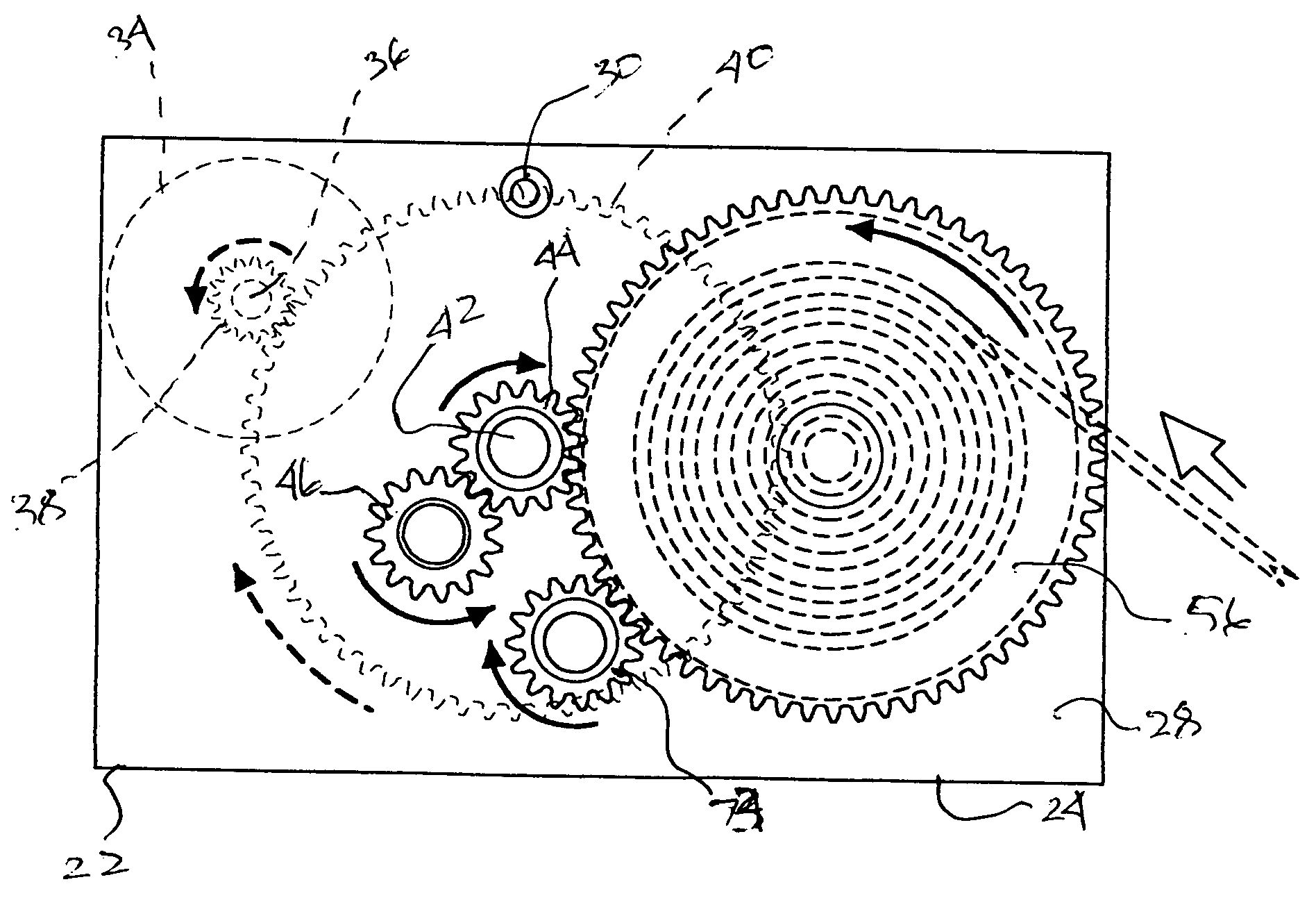
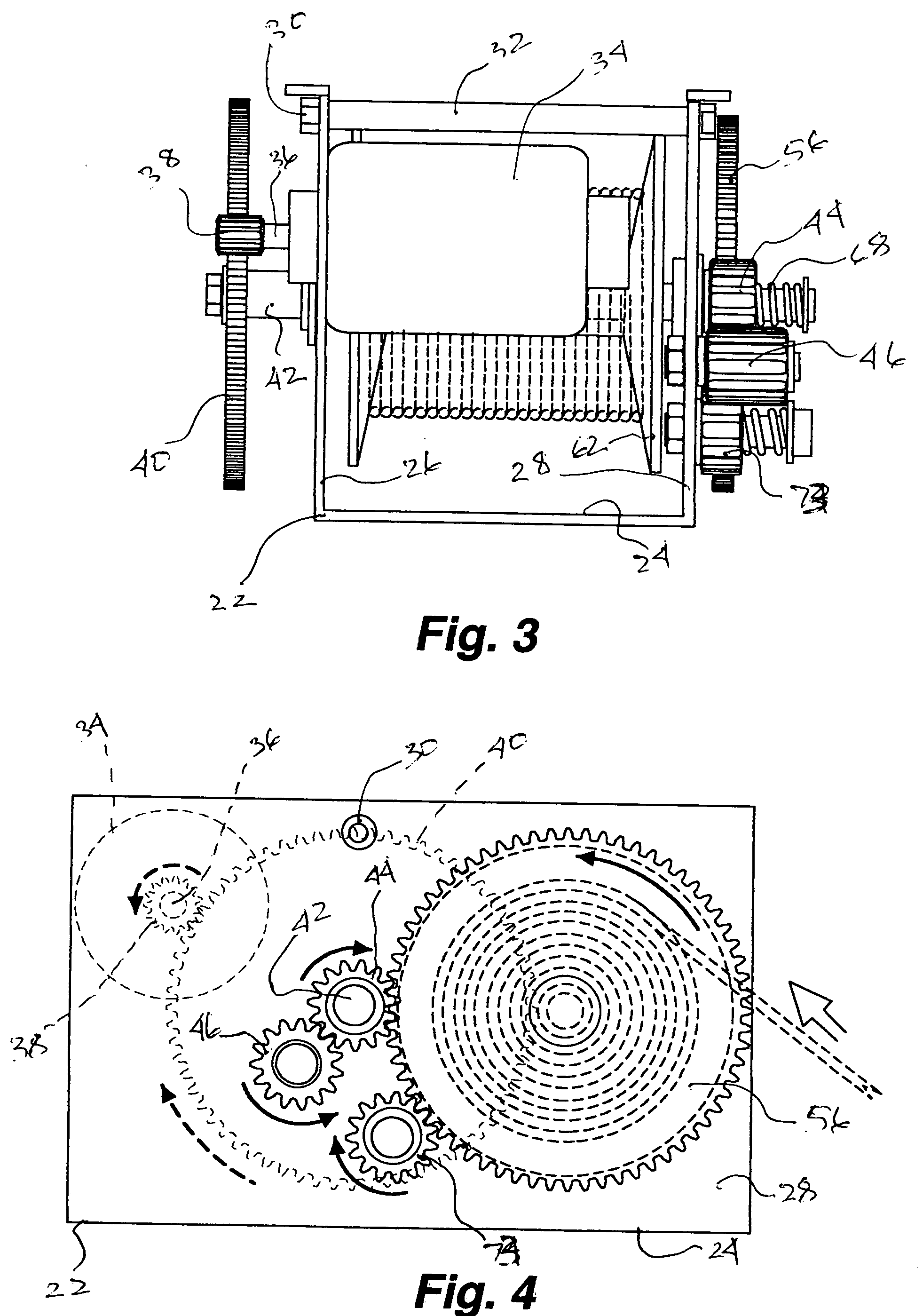
[0022] The windlass 14 itself as best seen in FIGS. 3-11, without an outer covering or housing 20 seen in FIGS. 1 and 2, includes a frame 22 of generally U-shaped transverse cross section having a base 24 that can be secured to the deck of the boat 12 and left and right upstanding side walls 26 and 28, respectively. The side walls are bridged along a top edge with a bolt 30 and surrounding spacer sleeve 32 to provide strength and rigidity to the frame. A reversible electric motor 34 is mounted adjacent the front and near the top of the left side wall 26 and has a drive shaft 36 protruding outwardly from the left side wall. A toggle swi...


PUM


Abstract

A freefall-type windlass includes appropriate gearing for moving the windlass spool in a retrieve direction to wrap anchor cable thereabout or to permit the anchor to drop by gravity thereby unwrapping the anchor cable from the spool. A governor gear is incorporated into the windlass to restrict the rate at which the spool can rotate when the anchor is being paid out thereby avoiding entanglement of the anchor cable and malfunctioning of the windlass.

Description

BACKGROUND OF THE INVENTION [0001] 1. Field of the Invention [0002] The present invention relates generally to windlasses and in particular to a windlass which is motor driven to raise an anchor or other heavy object while allowing the object to freefall in a controlled manner through use of a governor on the cable spool of the windlass. [0003] 2. Description of the Relevant Art [0004] Recreational boats, as well as other crafts of similar size, frequently include power operated windlasses or anchor winches capable of automatically dropping, locking, or raising an anchor. Sometimes, the motor is reversible to raise the anchor or lower the anchor in a controlled manner, but many times the anchor is lowered through gravity so that the anchor freefalls through the water to its destination. [0005] As will be appreciated, when an anchor and its cable is allowed to drop by gravity at a relatively fast speed, the cable will sometimes overrun the spool on which it is wrapped throwing the ca...

Claims


Application Information

Patent Timeline
Patent Type & Authority Applications(United States)
IPC IPC(8): B66D1/14
CPCB63B21/22B66D1/16
Inventor VERAKIS, DAVID C.MCBREEN, DAVID C.
Why Eureka
Try Eureka