
Wheel and a bicycle equipped with such wheel

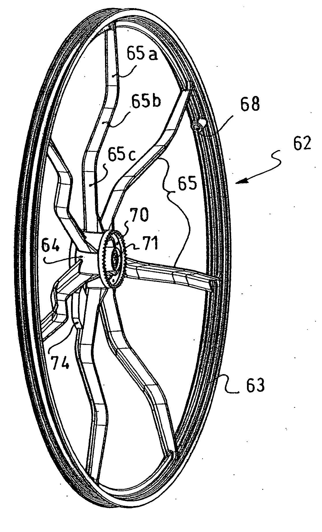
a technology of a wheel and a rotary portion, which is applied in the direction of cycle equipment, mechanical vibration separation, cycle, etc., can solve the problems of large wheel diameter, reduced rotary portion lengthwise, and low efficiency, so as to achieve a better compromise between performance and versatility, and the effect of convenient us

Inactive Publication Date: 2006-05-25
SALOMON SA
View PDF10 Cites 33 Cited by
  • Summary
  • Abstract
  • Description
  • Claims
  • Application Information

AI Technical Summary

Benefits of technology

[0019] An object of the present invention is to provide a new type of bicycle that offers a better compromise between performance and versatility, and which is easier to use than a conventional bicycle.

Problems solved by technology

However, a wheel having a large diameter does not offer the best compromise for a multipurpose bicycle.
Indeed, its weight and inertia are relatively substantial.
As a result, the rotary portion of the wheel tends to be reduced lengthwise due to the reduction of the dish of the wheel, which is not favorable for the rigidity of the wheel.
Another problem that arises for a bicycle relates to its transportation and storage.
A problem also arises when storing the bicycle in a small space.
However, with the current bicycles having the hub mounted on the fork of the frame, mounting and demounting are not practical because of the need to remove and then reposition the chain, and to adjust the braking system, to accommodate the mounting and demounting of the wheel.
The problem of mounting and demounting the wheel also arises in the case of a flat tire.
Under these conditions, they could not be used with single-arm forks, as the extent of the overhang would indeed be excessive.
Furthermore, the mass and inertia of these compression-spoke wheels increase with the diameter and, inversely, their rigidity deteriorates with the increase in the diameter.
Under these conditions, a 700 mm compression spoke wheel would not be satisfactory with respect to weight and rigidity.

Method used


Image

  • Wheel and a bicycle equipped with such wheel
  • Wheel and a bicycle equipped with such wheel
  • Wheel and a bicycle equipped with such wheel

Examples


Embodiment Construction

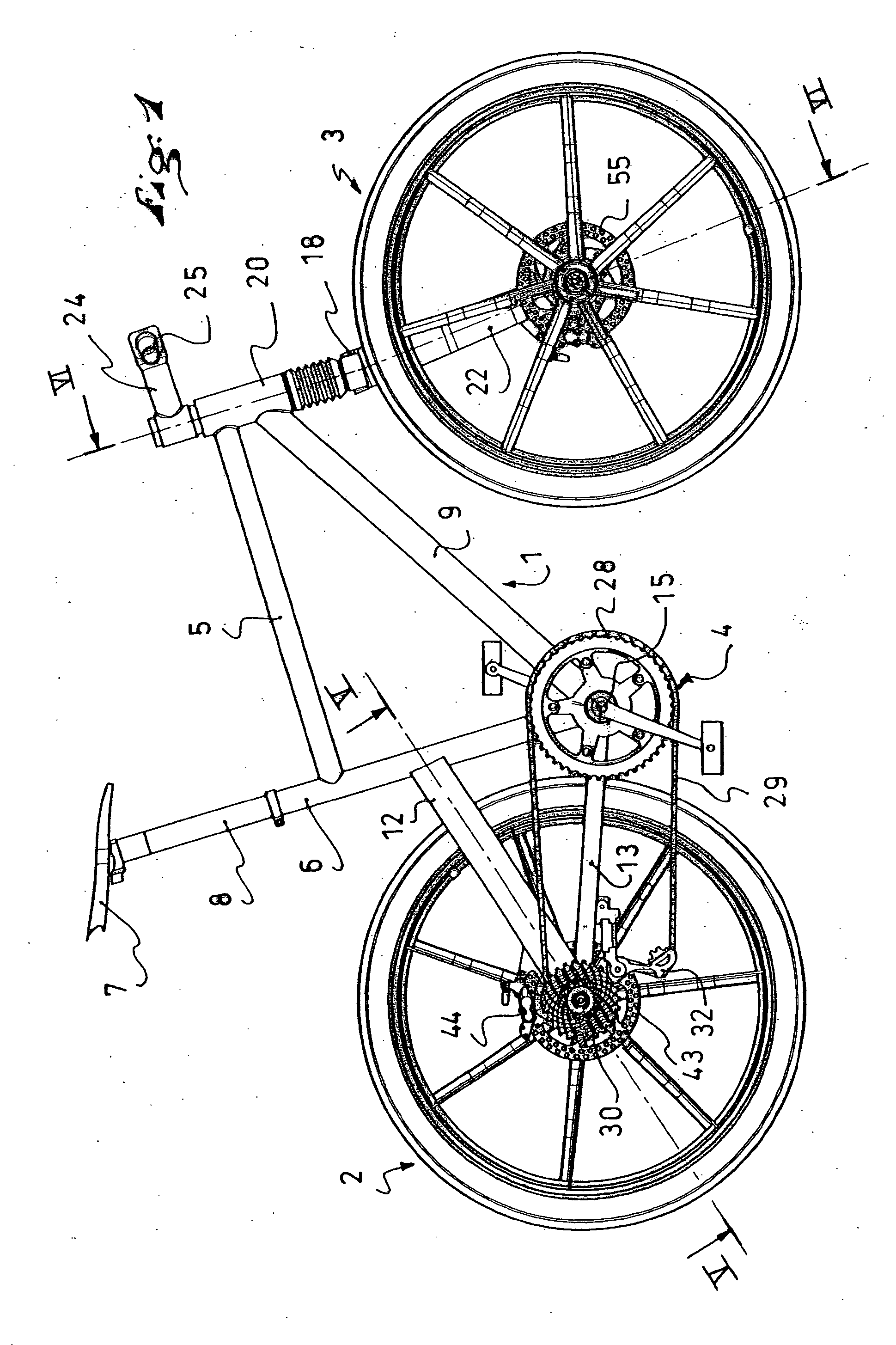
[0034] The bicycle illustrated in FIG. 1 includes a frame 1, a rear wheel 2, a front wheel 3, and a transmission assembly 4.

[0035] The frame has a base structure 5 formed of tubes or sections assembled to one another by any appropriate means, particularly by welding or by glue / adhesive. The sections or tubes are metallic, made of steel or aluminum alloy, for example. The structure could also be made of a composite material, such as carbon fibers embedded in a resin matrix.

[0036] In a known manner, the structure 5 includes a seat tube 6 for supporting the seat 7 and its seat post 8, as well as a down tube 9.

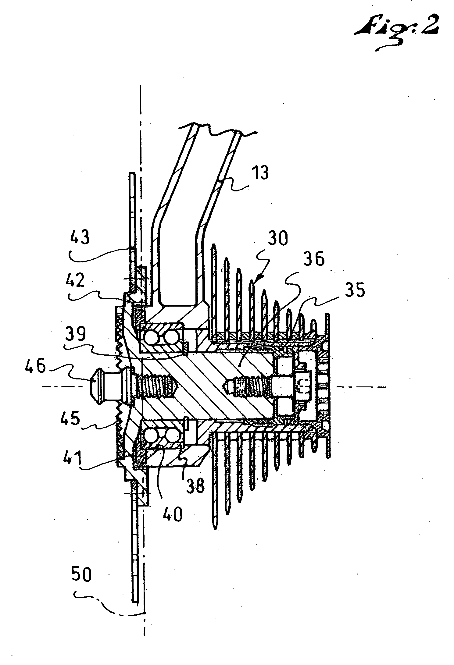
[0037] At the rear, the structure 5 has a single-arm wheel-supporting fork. The fork here includes a seat stay 12 and a chain stay 13 that converge toward the center of the rear wheel, on only one side of the wheel.

[0038] Conventionally, the chain stay 13 is coupled to the down tube 9 in the area of a crankset case that bears the axis of rotation 15 of the crankset.

[0039] At ...


PUM

PropertyMeasurementUnit
Diameteraaaaaaaaaa
Diameteraaaaaaaaaa
Diameteraaaaaaaaaa

Abstract

A bicycle that includes front and rear single-arm forks enabling the front and rear wheels to be mounted and demounted from the frame of the bicycle without necessitating the removal or repositioning of a transmission element, such as a chain, or the brake, if the bicycle is so equipped, each of the wheels including at least one flexibly and compressively rigid element connecting the central hub and the rim, such elements being asymmetrical with respect to a radial median plane defined by the rim, so that the hubs of the wheels are axially off-centered in relation to the radial median plane of the rim, while the radial median plane of the rims coincides with the general median plane of the frame. The invention is also directed to the wheel of the bicycle.

Description

CROSS-REFERENCE TO RELATED APPLICATIONS [0001] This application is a continuation of PCT International Patent Application No. PCT / FR2004 / 001312, filed on May 27, 2004, the disclosure of which is hereby incorporated by reference thereto in its entirety, and the priority of which is claimed under 35 U.S.C. §120, pursuant to the provisions of 35 U.S.C. §363.[0002] This application claims priority under 35 U.S.C. §119 of French Patent Application No. 03.06547, filed on May 28, 2003, the disclosure of which is hereby incorporated by reference thereto in its entirety. BACKGROUND OF THE INVENTION [0003] 1. Field of the Invention [0004] The invention relates to a bicycle and to a wheel to be used on such a bicycle. [0005] 2. Description of Background and Relevant Information [0006] A traditional bicycle includes a frame, front and rear wheels, a transmission assembly, a steering assembly, and usually a braking assembly. [0007] Currently, there are standards used for reference by manufacture...

Claims


Application Information

Patent Timeline
IPC IPC(8): B06B3/00B60B1/06B60B19/00B62K25/00
CPCB60B1/003B60B1/06B60B5/02B60B27/0005B60B27/026B60B2310/204B60B2360/104B60B2360/106B60B2360/32B60B2360/341B60B2900/531B60Y2200/13B62K25/005
Inventor MERCAT, JEAN-PIERREHILLAIRET, JEAN-MARC
Owner SALOMON SA
Learn More