Surface acoustic wave touch panel and system of the same

a technology touch panel, which is applied in the field of surface acoustic wave touch panel and system, can solve the problems of capacitance-type touch panel, limited space for accommodating input devices in such electronic products, and reduced brightness and contrast of display screen, etc., and achieves high throughput, reduced output signal amplitude, and high resolution of touch panel

Inactive Publication Date: 2006-05-25
IND TECH RES INST
View PDF6 Cites 58 Cited by
  • Summary
  • Abstract
  • Description
  • Claims
  • Application Information

AI Technical Summary

Benefits of technology

[0015] In light of the above drawbacks in the prior art, an objective of the present invention is to provide a surface acoustic wave touch panel and a system of the same so as to provide high resolution and high throughput.
[0016] Another objective of the present invention is to provide a surface acoustic wave touch panel and a system of the same, which have simple fabrication processes.
[0019] Therefore, the surface acoustic wave touch panel and the system of the same according to the present invention have advantages such as high throughput, high resolution of the touch panel, and simple fabrication processes of the touch panel.

Problems solved by technology

However, since such conventional input devices are not space-economic when in use and need to be driven by complex programs, another type of input device has been developed and is named touch panel that is a combination of the input device and a display screen.
As electronic products are developed to have compact size, light weight, and complex functions, a space for accommodating an input device in such electronic product is very limited.
The resistance-type touch panel has a drawback of low light transmittance and thus reduces brightness and contrast of the display screen.
The capacitance-type touch panel is liable to changes in different temperature, humidity, and grounding conditions and thus has poor stability.
This is disadvantageous for the control system 11 to analyze the output signals.
However, the high performance A / D converter is expensive, making the cost of the touch panel greatly raised.
However, the touch panel with an array of emitting transducers and an array of receiving transducers makes its structure relatively complex, and the resolution thereof directly relates to the signal analysis method and is the same as a pitch between adjacent transducers.
Consequently, under limitation on the fabrication technology and cost, it is difficult to provide products with high resolution.

Method used


Image

  • Surface acoustic wave touch panel and system of the same
  • Surface acoustic wave touch panel and system of the same
  • Surface acoustic wave touch panel and system of the same

Examples


first embodiment

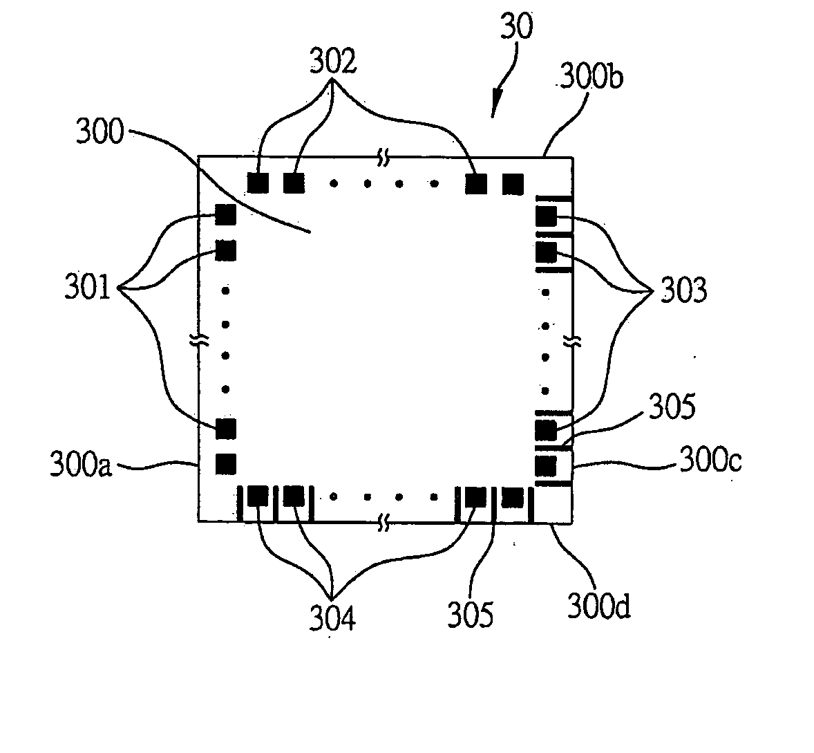
[0036] Referring to FIG. 3A showing a top view of the surface acoustic wave touch panel according to the present invention, this surface acoustic wave touch panel 30 comprises a substrate 300 having a plurality of emitters 301, 302 and a plurality of receivers 303, 304.

[0037] The substrate 300 is a thin plate, such as a transparent substrate. The plurality of emitters 301, 302 and the plurality of receivers 303, 304 are formed by depositing piezoelectric films on a surface of the substrate 300, wherein the plurality of emitters 301 are disposed sequentially as a one-dimensional array on an edge 300a of the substrate 300, and the plurality of emitters 302 are disposed sequentially as a one-dimensional array on an edge 300b of the substrate 300 adjacent to the edge 300a. The plurality of receivers 303 are arranged sequentially as a one-dimensional array on an edge 300c of the substrate 300, and the plurality of receivers 304 are arranged sequentially as a one-dimensional array on an e...

second embodiment

[0051]FIG. 4B shows a system applied with the surface acoustic wave touch panel 30′ according to of the present invention. This embodiment of FIG. 4B is similar in working principles to the above embodiment of FIG. 4A. Thus only the differences between this embodiment and the above embodiment are described below for the sake of simplicity.

[0052] The I / O controlling unit 32′ produces a signal S1 to excite the emitters T1 to T64 sequentially in a multiplex manner to emit surface acoustic waves, and also produces a signal S2 to excite the emitters T1′ to T64′ sequentially in a multiplex manner to emit surface acoustic waves respectively. The single receiver 303′ and the single receiver 304′ receive the surface acoustic waves from the emitters T1 to T64 and the emitters T1′ to T64′ and convert the received surface acoustic waves into output signals f, f′. The detecting unit 33′ picks up the output signals f, f′ from the receivers 303′, 304′ according to signals S3, S4 transmitted from ...


PUM


Abstract

A surface acoustic wave touch panel and a system of the same are provided. The system includes the touch panel, an input / output (I / O) controlling unit, a detecting unit, and a signal processing unit. The touch panel includes a substrate on which at least one first emitter and at least one second emitter are provided on two adjacent edges thereof, and at least one first receiver and at least one second receiver are provided on the other two adjacent edges of the substrate. The I / O controlling unit controls the emitters to emit signals, and controls the detecting unit to pick up output signals from the receivers. The signal processing unit uses a neural network to determine an amplitude-reduction feature of any of the output signals so as to identify a position being touched on the touch panel. The touch panel is provided with high resolution and high throughput.

Description

FIELD OF THE INVENTION [0001] The present invention relates to surface acoustic wave touch panels and systems of the same, and more particularly, to a surface acoustic wave touch panel composed of emitters and receivers made of piezoelectric films, and a system of the surface acoustic wave touch panel. BACKGROUND OF THE INVENTION [0002] With the prevalence of computers, keyboards, and mice have become generally accepted input devices. However, since such conventional input devices are not space-economic when in use and need to be driven by complex programs, another type of input device has been developed and is named touch panel that is a combination of the input device and a display screen. [0003] Touch panel is a user-friendly input device, which allows commands to be inputted simply by using a finger or touch pen to touch and select specific areas on the panel. As electronic products are developed to have compact size, light weight, and complex functions, a space for accommodatin...

Claims


Application Information

Patent Timeline
Patent Type & Authority Applications(United States)
IPC IPC(8): G09G5/00
CPCG06F3/0436
Inventor CHOU, YUAN-FANGHWU, KEH-LONGTIEN, CHING-CHENG
Owner IND TECH RES INST
Why Eureka
Try Eureka