Scalable zig-zag laser amplifier

a laser amplifier and zig-zag technology, applied in lasers, laser cooling arrangements, laser details, etc., can solve the problems of large volume and weight requirements of such a system, and limited total output power of this device, so as to improve the cooling system and improve the effect of efficiency

Active Publication Date: 2006-05-25
NORTHROP GRUMMAN SYST CORP
View PDF13 Cites 37 Cited by
  • Summary
  • Abstract
  • Description
  • Claims
  • Application Information

AI Technical Summary

Problems solved by technology

However, the total output power of this device is limited by its small cross sectional area, which is in turn limited by the need to keep the slab thickness small (a few millimeters) to provide adequate removal of residual heat deposited in the slab.
Consequently, the size, weight, complexity, and cost of such a system would be excessive for many applications.
This approach, however, suffers from large volume and weight requirements, when scaled to incorporate many slabs.
Although this scheme is effective at mitigating the OPD within the plates, a major difficulty is encountered from the OPD produced by temperature gradients in the flowing liquid.
In summary, any attempt to scale the device of FIG. 1 to higher output powers is rendered extremely difficult by the sheer bulk associated with multiple devices of this type, each of which must be cooled and have its output beam combined with others to produce a high power composite output.
One serious problem with this approach was that the effective path length of the pump beams was limited by the thickness of the slab.
Increasing the slab thickness allowed for more pump energy to be absorbed, but the thicker slab had significant thermal gradient problems.
Although the end-pumped zig-zag configuration makes relatively efficient use of pump power, it does not satisfy the need for a solid state laser architecture that is scalable to much higher powers, on the order of 100 kw or higher.
Combining multiple zig-zag lasers of the type shown in Pat. No. 6,094,297 results in an extremely bulky structure.
Combining the output beams of the multiple lasers is also rendered difficult by the bulk and necessary spacing of the individual devices.
Moreover, the resulting structure would be impractically large for the powers desired.. Ideally, a high-power laser for military or commercial applications should be conveniently portable, or at least movable on a conventional vehicle.

Method used


Image

  • Scalable zig-zag laser amplifier
  • Scalable zig-zag laser amplifier
  • Scalable zig-zag laser amplifier

Examples


Embodiment Construction

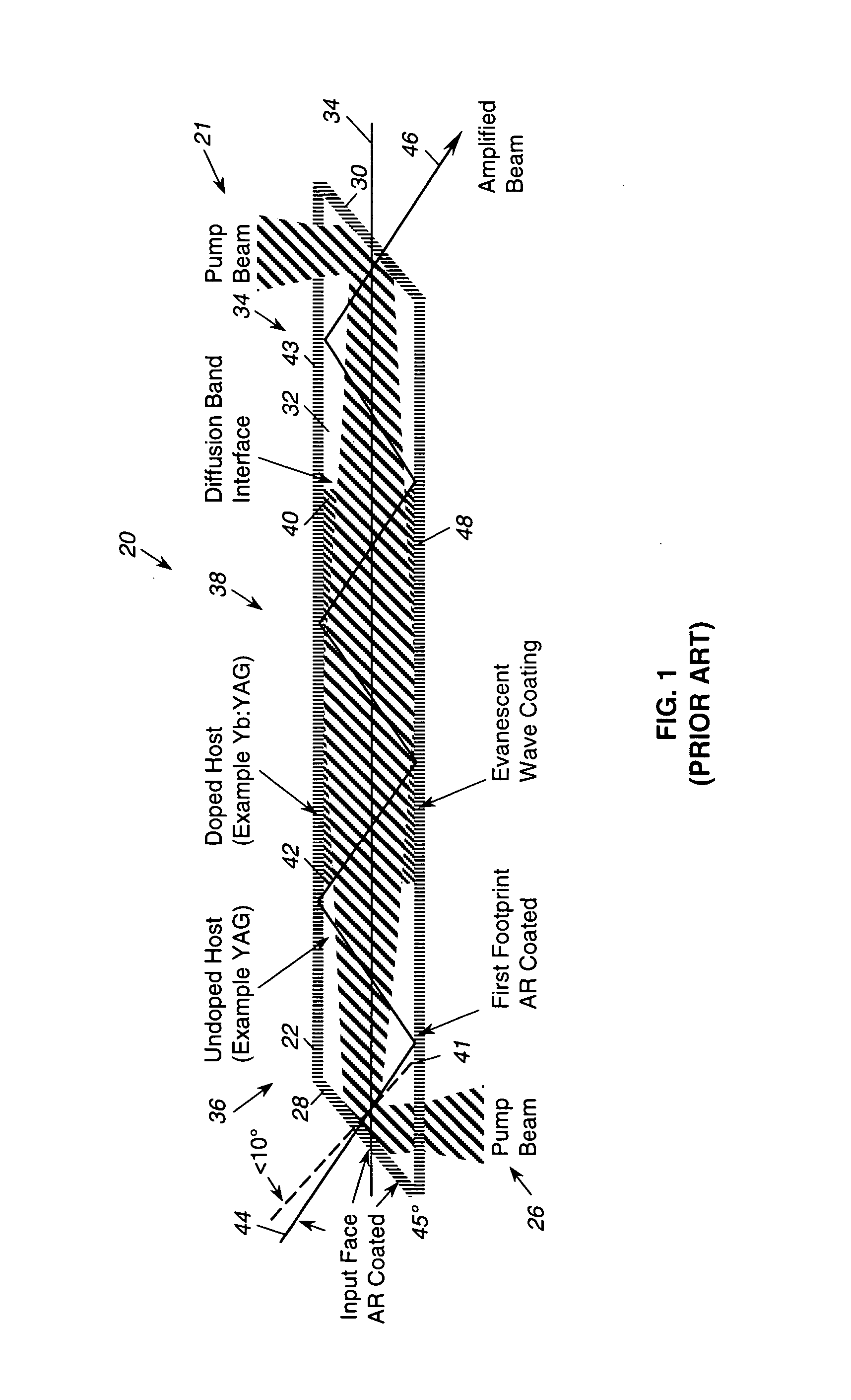
[0041] As shown in the drawings for purposes of illustration, the present invention pertains to a sold state zig-zag amplifier configuration that is readily scalable to very high output powers. As discussed above, zig-zag laser amplifiers of the prior art cannot be easily scaled to higher powers without using an extremely bulky structure, and even then the resulting multiple beams cannot be easily combined into a single small beam aperture.

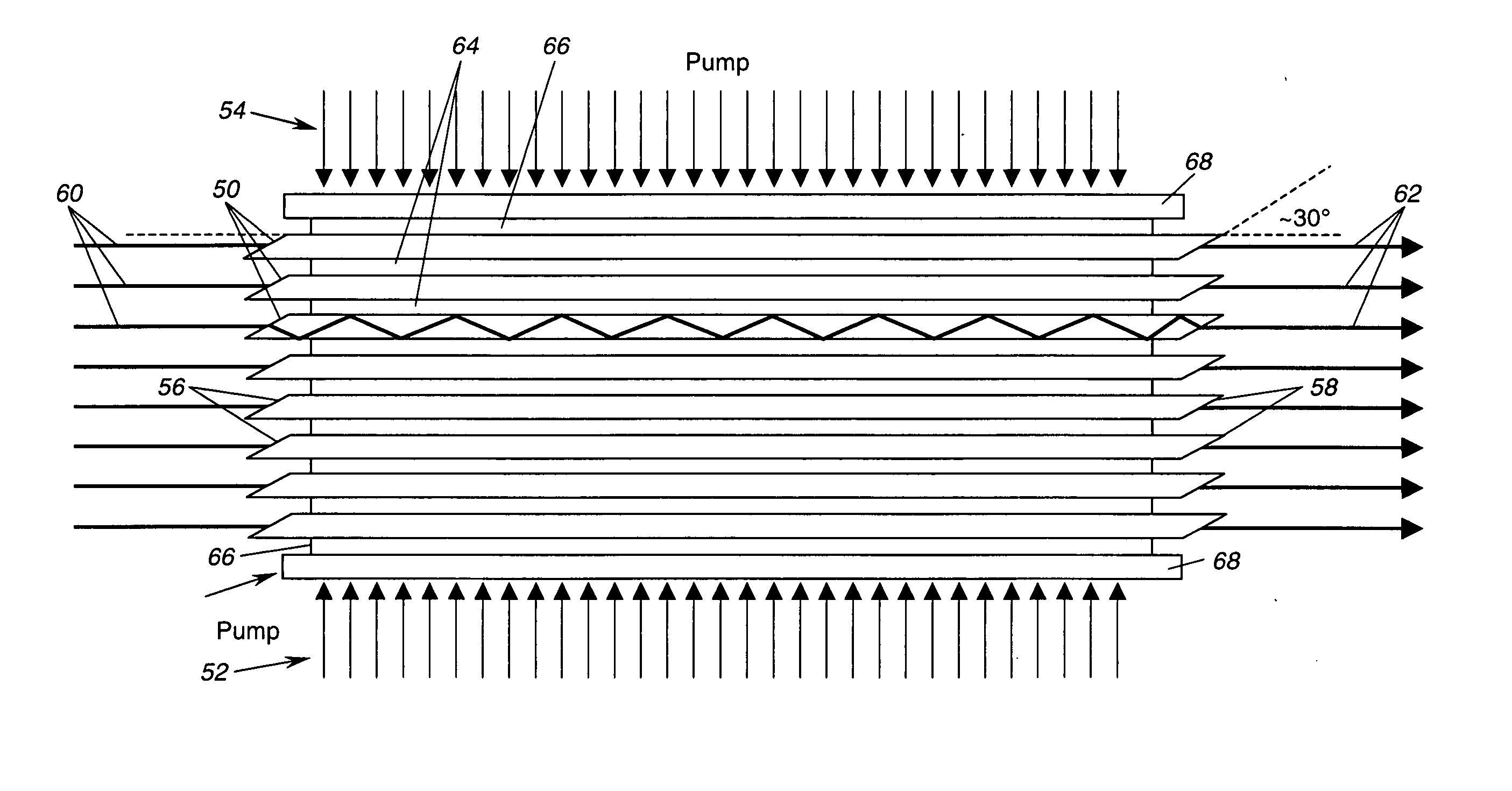
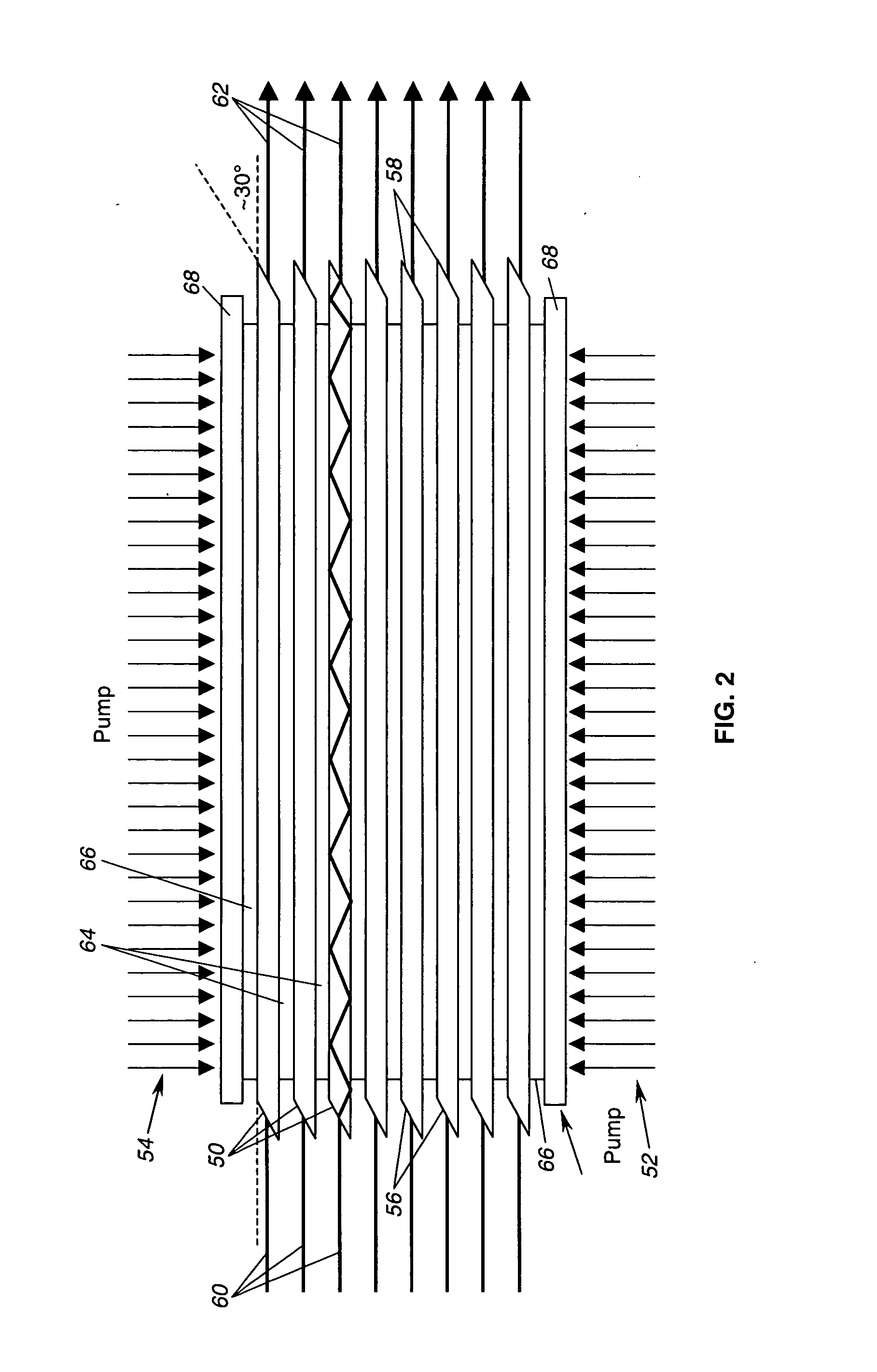
[0042] In accordance with the present invention, and as shown generally in FIG. 2, scaling of zig-zag amplifiers to higher powers is conveniently achieved by employing side pumping of stacked slabs and a common cooling system. As shown in the figure, multiple solid state slab lasers 50 are stacked in close proximity and arrays 52, 54 of pump lasers are directed from the sides of the outermost slabs. Pump power from the arrays 52, 54 of pump lasers is focused by appropriate optical components for collimation and shaping of the pump beams. End face...


PUM


Abstract

A solid state laser amplifier architecture in which multiple zig-zag slab laser amplifiers (50) are stacked together, side-pumped using a common pump source (52, 54), and cooled with a common cooling system. The stack of zig-zag slabs (50) produces an array of sub-beams (62) that can be combined coherently into a single composite output beam. Variations in pump power absorption through the stack are mitigated by selection of doping levels for the slabs (50). The composite output beam is sufficiently symmetrical to be directed through conventional optics of circular cross section. Multiple stacks may be arranged in a two-dimensional array to obtain even higher output powers.

Description

BACKGROUND OF THE INVENTION [0001] This invention relates generally to high power solid state lasers and, more particularly, to solid state laser amplifiers of the zig-zag type, in which a light beam is confined laterally in a solid state slab of doped material, and is subject to repeated internal reflections from parallel faces of the slab. A zig-zag laser amplifier of the prior art is exemplified by the one disclosed in U.S. Pat. No. 6,094,297, to lnjeyan et al., entitled “End Pumped Zig-Zag Slab Laser Gain Medium.”[0002] In the configuration described in Pat. No. 6,094,297, a slab of solid state lasing material employs end pumping, which is to say that a pump beam is launched into one or both ends for the slab, and a relatively high overall efficiency is attained by passing the amplified light through the slab in a zig-zag manner. The pump energy is launched into the slab as a narrow beam that passes through one of the parallel faces of the slab and reflects from an end face angl...

Claims


Application Information

Patent Timeline
Patent Type & Authority Applications(United States)
IPC IPC(8): H01S3/04H01S3/091
CPCH01S3/0606H01S3/063H01S3/08095H01S3/0941H01S3/2308H01S3/2333H01S3/2341H01S3/2383H01S2301/02
Inventor ROTHENBERG, JOSHUA E.
Owner NORTHROP GRUMMAN SYST CORP
Why Eureka
Try Eureka