Venturi fan

a fan and venturi technology, applied in the field of fans, can solve the problems of increasing the amount of air available to the fan, and achieve the effect of reducing noise, avoiding the generation of some fan noise, and reducing the noise of the fan

Inactive Publication Date: 2006-05-25
PATTERSON FAN
View PDF14 Cites 7 Cited by
  • Summary
  • Abstract
  • Description
  • Claims
  • Application Information

AI Technical Summary

Benefits of technology

[0006] According to its major aspects and briefly recited, the present invention is a venturi fan capable of producing a significant, directed flow of air but with significantly reduced noise compared to prior art venturi fans. The present fan has a body comprised of a generally cylindrical wire basket for carrying a motor and fan blade assembly, and a flared intake carried at the rear of the wire basket. Preferably, the front of the basket carries an exit channel, which may also have a flare but is otherwise preferably substantially cylindrical in shape. The rear-flared intake allows for a smooth feed of air into the basket and past the motor and the air-accelerating fan blade assembly. The wire basket, in a preferred embodiment, acts as a conduit for the flow-path air but also admits additional air into the flow path and channels the flow of air produced by the fan while allowing fan noise to dissipate through the sides. The basket also avoids generation of some fan noise and is a safety feature, preventing injury in its role as both the side and rear finger guard.
[0007] An important feature of the present invention is the relatively open sides of the present fan, compared to prior art venturi fans. The relatively open sides contribute significantly and in a number of ways to noise reduction, chiefly by allowing noise to escape, while not significantly degrading the flow of air. Indeed, the openness of the sides increases the amount of air available to the fan.
[0008] Additionally, the combination of the rear flare intake and the wire basket is a significant feature of the present invention. This combination allows the flow of air generated by the fan blade assembly to be created and directed significant distances with little diffusion.
[0009] The use of the wire basket to support the motor and fan blade assembly is yet another important feature of the present invention. This arrangement reduces material, weight and obstructions to air flow while providing a sufficiently sturdy securement for the motor and fan blade assembly.

Problems solved by technology

Indeed, the openness of the sides increases the amount of air available to the fan.

Method used


Image

  • Venturi fan
  • Venturi fan
  • Venturi fan

Examples


Embodiment Construction

[0018] The present invention is an improvement in venturi-style fans. Venturi fans direct a significant quantity of air in a forward direction and are suitable for large buildings such as warehouses. Unfortunately, prior art venturi fans are relatively noisy.

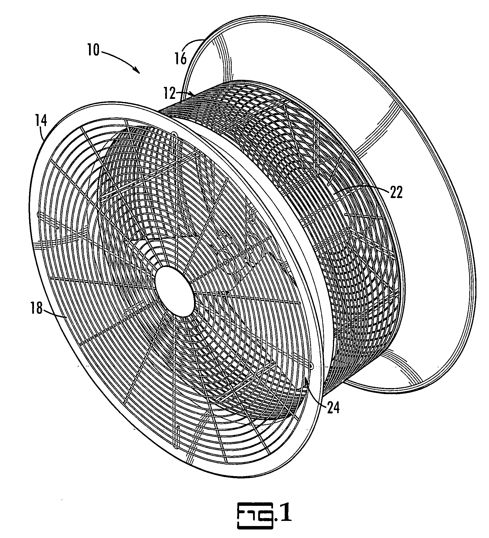
[0019]FIG. 1 illustrates in perspective the present venturi fan 10. Fan 10 has a housing 12 that is flared on both the front 14 and the rear 16, and has a front finger guard 18. Inside housing 12 is a motor 22 and a fan blade assembly 24.

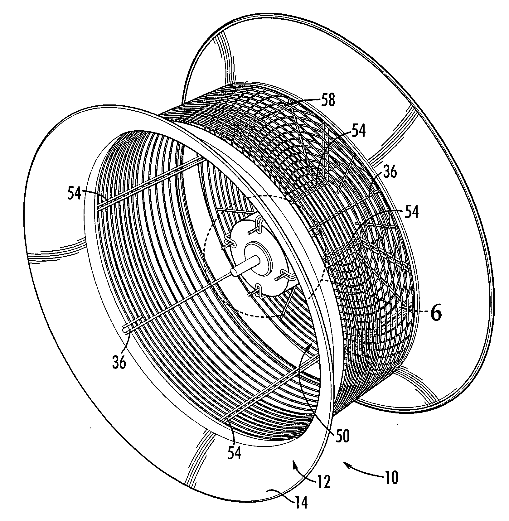
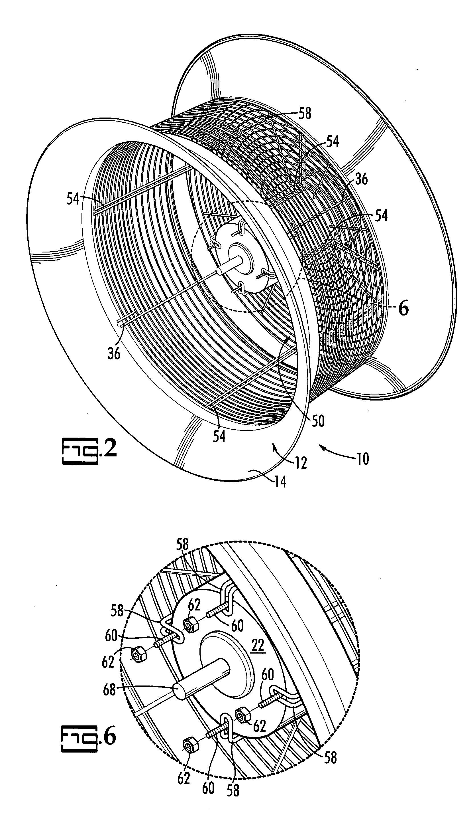
[0020] Referring now to FIG. 2, there is illustrated a side view of venturi fan 10 according to a preferred embodiment of the present invention. Fan 10 is rotationally symmetric so it appears the same from all sides. Unlike prior art venturi fans, venturi fan 10, shown in FIGS. 1-6 in its preferred embodiment, has an opening formed in the side wall 28, preferably a multiplicity of openings such as perforations or an array of slots, but, most preferably, a multiplicity of openings formed by spa...


PUM


Abstract

A venturi-type fan is composed of a wire basket between front and rear flares. The wire basket has a rear portion to which the motor and fan blade assembly is mounted. The rear flare controls the admission of air into the fan to reduce turbulence and allows the flow of air to be accelerated and directed forward in a slowly diffusing column. The openness of the sides of the present fan reduces the noise generally associated with close-sided venturi fans without degrading air movement characteristics

Description

CROSS REFERENCE TO RELATED PATENTS [0001] The present application claims priority to U.S. Provisional Application Ser. No. 60 / 630,113, filed Nov. 22, 2004, incorporated herein by reference.BACKGROUND OF THE INVENTION [0002] The present invention relates to fans generally, and to fans used in industrial and commercial settings in particular. [0003] The purpose of a fan is move air in order to ventilate and cool an area. In industrial and commercial environments, where air conditioning may be impractical, fans are vital to employees' health and comfort. [0004] There are several types of fans used in commercial and industrial environments. One type includes a fan blade enclosed within a wire frame housing or “cage”, sometimes mounted on a pedestal. The shaft of a motor outside the housing may project into the housing to turn the blades. These fans work fine in smaller quarters. Increasing the speed of the motor and the pitch of the blade allows this type of fan to throw more air, but i...

Claims


Application Information

Patent Timeline
Patent Type & Authority Applications(United States)
IPC IPC(8): F04B17/00
CPCF04D29/545F04D29/661
Inventor MOORE, MARKPATTERSON, VANCE M.SALISBURY, THOMAS
Owner PATTERSON FAN
Why Eureka
Try Eureka