Angular velocity detector having inertial mass oscillating in rotational direction

a technology of inertial mass and detector, which is applied in the direction of acceleration measurement using interia forces, turn-sensitive devices, instruments, etc., can solve the problems of difficult to make driving beams, unavoidable angular velocity detector structure, etc., and achieve the effect of easy design and manufactur

Inactive Publication Date: 2006-06-01
DENSO CORP
View PDF2 Cites 102 Cited by
  • Summary
  • Abstract
  • Description
  • Claims
  • Application Information

AI Technical Summary

Benefits of technology

[0012] The present invention has been made in view of the above-mentioned problem, and an object of the present invention is to provide an improved angular velocity detector having driving beams that can be easily designed and manufactured.

Problems solved by technology

However, it is unavoidable to make the structure of the angular velocity detector complex.
It is particularly difficult to make the driving beams 40 in precise dimensions that realize desired resonant frequencies in both directions.

Method used


Image

  • Angular velocity detector having inertial mass oscillating in rotational direction
  • Angular velocity detector having inertial mass oscillating in rotational direction
  • Angular velocity detector having inertial mass oscillating in rotational direction

Examples


Embodiment Construction

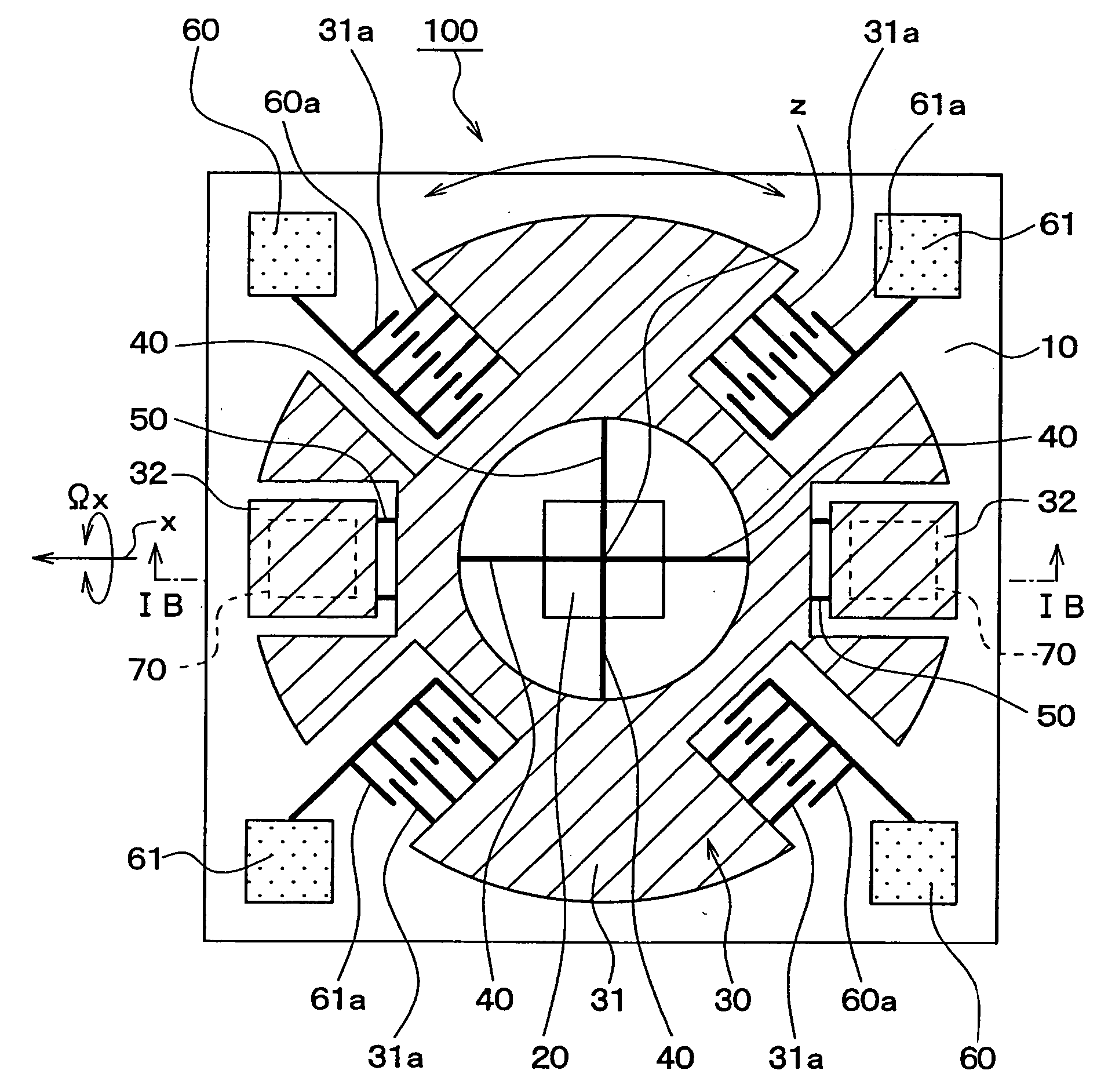
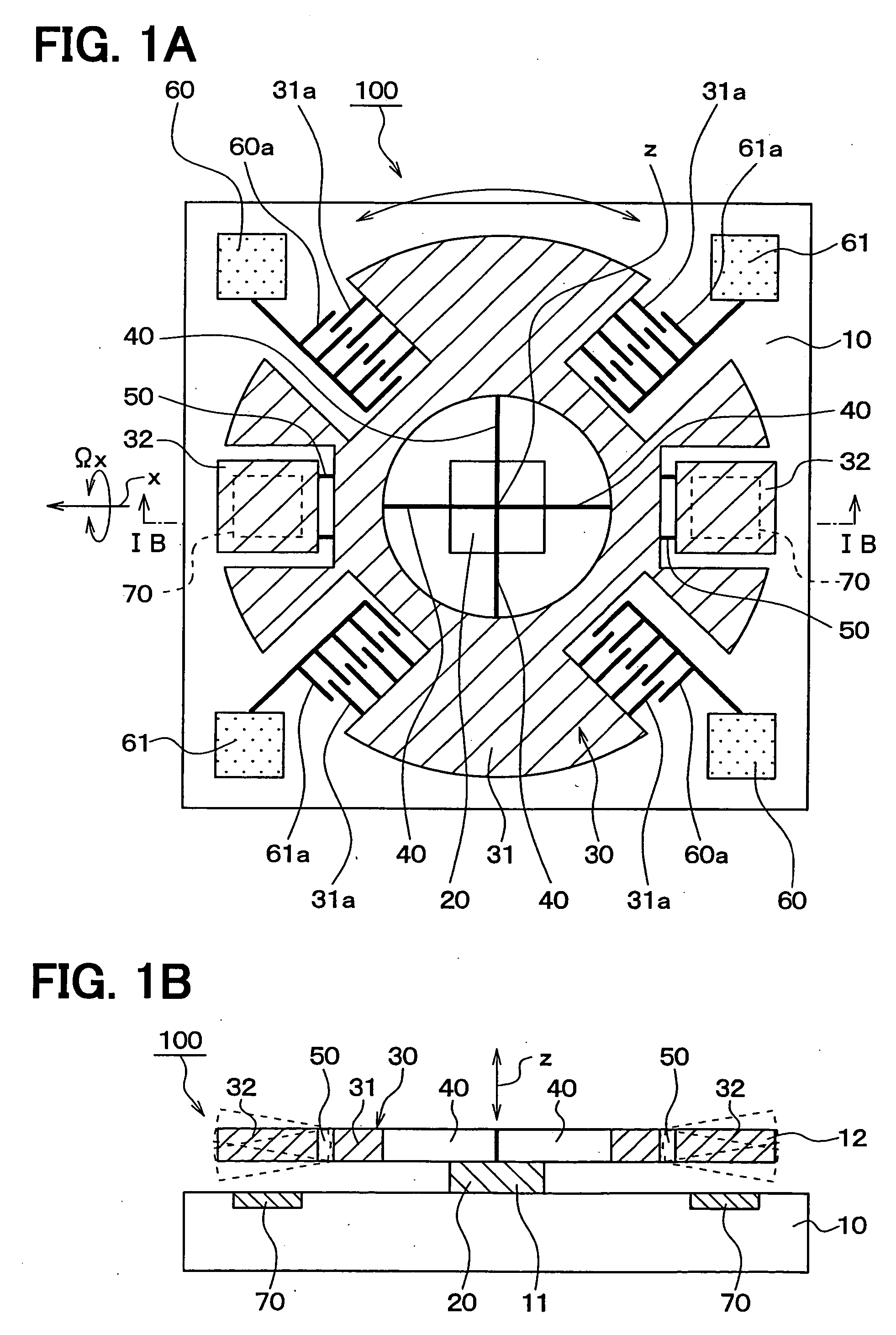
[0024] A first embodiment of the present invention will be described with reference to FIGS. 1A and 1B showing a plan view and a cross-sectional view of an angular velocity detector 100 of the present invention, respectively. Hatching in FIG. 1A does not mean a cross-section but shows a top plane of components. In order to clearly differentiate an inertial mass 30 from driving electrodes 60, 61, the former is hatched and the latter is dotted.

[0025] The angular velocity detector 100 is manufactured from a three-layer plate composed of a substrate 10, a sacrifice layer 11 such as a silicon oxide layer and a semiconductor layer 12 such as an epitaxial poly-silicone layer, laminated in this order. The detector 100 is manufactured by known semiconductor processing technologies. Portions of the sacrifice layer 11 are removed by etching to separate an inertial mass 30 from the substrate 10. Alternatively, the angular velocity detector 100 may be manufactured from a silicon-on-insulator su...


PUM


Abstract

An angular velocity detector includes a disk-shaped inertial mass supported on a substrate via driving beams and a second mass connected to the inertial mass via detecting beams. The inertial mass is oscillated in its rotational direction around a center axis (z) by an electrostatic force. When an angular velocity around a detection axis (x), which is perpendicular to the center axis (z), is imposed on the second mass while the inertial mass is oscillating, the second mass displaces in the direction parallel to the center axis (z). A capacitance between the second mass and the substrate changes according to the displacement of the second mass. The angular velocity is detected based on the changes in the capacitance. Since the driving beams allow the inertial mass to oscillate only in the rotational direction, the driving beams can be easily designed and manufactured.

Description

CROSS-REFERENCE TO RELATED APPLICATION [0001] This application is based upon and claims benefit of priority of Japanese Patent Application No. 2004-348543 filed on Dec. 1, 2004, the content of which is incorporated herein by reference. BACKGROUND OF THE INVENTION [0002] 1. Field of the Invention [0003] The present invention relates to an angular velocity detector having an inertial mass oscillating in its rotational direction. [0004] 2. Description of Related Art [0005] The angular velocity detector of this type detects an angular velocity imposed around a detection axis that is perpendicular to a rotational axis of an inertial mass. The inertial mass is displaced by Coriolis force imposed on the inertial mass when the inertial mass is oscillating around its rotational center. An example of the angular velocity detector of this type is disclosed in JP-A-2001-99855. [0006] There is another type of the angular velocity detector using the Coriolis force, in which an inertial mass vibra...

Claims


Application Information

Patent Timeline
Patent Type & Authority Applications(United States)
IPC IPC(8): G01P9/04G01C19/56G01C19/5712
CPCG01C19/5719G01C19/5712G01P3/44
Inventor HIGUCHI, HIROFUMI
Owner DENSO CORP
Why Eureka
Try Eureka