Barcode imaging and laser scanning systems having improved visual decoding indication

a laser scanning and barcode technology, applied in the field of barcode imaging and laser scanning systems, can solve the problems of insufficient audible indicators, inability to foolproof, and inability to collect data through imaging or laser scanning processes,

Active Publication Date: 2006-06-01
SYMBOL TECH LLC
View PDF6 Cites 32 Cited by
  • Summary
  • Abstract
  • Description
  • Claims
  • Application Information

AI Technical Summary

Benefits of technology

[0025] It is contemplated that different timing arrangements (i.e., blinking speeds) for causing the turning off and on of the at least one LED or all the LEDs of the illumination system and aiming system in barcode imaging / decoding systems, as well as the projected laser beam in laser barcode scanning / decoding systems and imaging / decoding systems, can provide visual indication to the user of additional information, such as the switching of barcode scanner from the trigger-operated mode to the hands-free mode and vice versa; a no-decode condition; loss of communication between a terminal and the barcode scanner; the mode the barcode scanner is currently operating in; the barcode is misaligned within the field of view of the barcode scanner; the symbology of the imaged or laser scanned barcode is not recognizable; a low battery condition in the case of a wireless barcode scanner powered by a battery; etc.

Problems solved by technology

The audible indicator, however, is not always adequate, such as, for example, in noisy environments, or where it must be turned off due to the desirability to maintain silence or where the beeping sound is annoying or distracting to people nearby.
This, however, is not foolproof as the illumination system or laser beam system might have been turned off for reasons other than a decode, such as the elapsed time limit having been exceeded or because of the operator accidentally relaxing pressure on the trigger switch, both of which would result in the illumination system or laser beam system being turned off without the barcode having been decoded.
Whenever this occurs, the integrity of the data being collected by the imaging or laser scanning process is compromised.
One problem is that the spot of light is generally small, and due to tolerances in the optical system that projects it, the spot of light does not always shine exactly at the center of the reading field of the barcode scanner.
The result of the latter is that the spot of light will sometimes miss the object being scanned, especially if the object is small.
If the spot of light misses the object, the user will typically not see the spot of light and might assume the barcode was not decoded, resulting in a second unwanted attempt to scan the same barcode.
Further, another problem is that the additional optical system for projecting the spot of light adds cost and size to the barcode scanner.
A problem with such prior art barcode imaging systems, is that before an object is placed in front of the hands-free barcode scanner, the illumination system is turned off, so there is no visual guide for the user to know exactly where the barcode should be positioned for imaging.
Additionally, since the spot of light is continuously projected, it can no longer serve the other function of visually indicating a decode by turning on only after a decode has occurred.

Method used


Image

  • Barcode imaging and laser scanning systems having improved visual decoding indication
  • Barcode imaging and laser scanning systems having improved visual decoding indication
  • Barcode imaging and laser scanning systems having improved visual decoding indication

Examples


Embodiment Construction

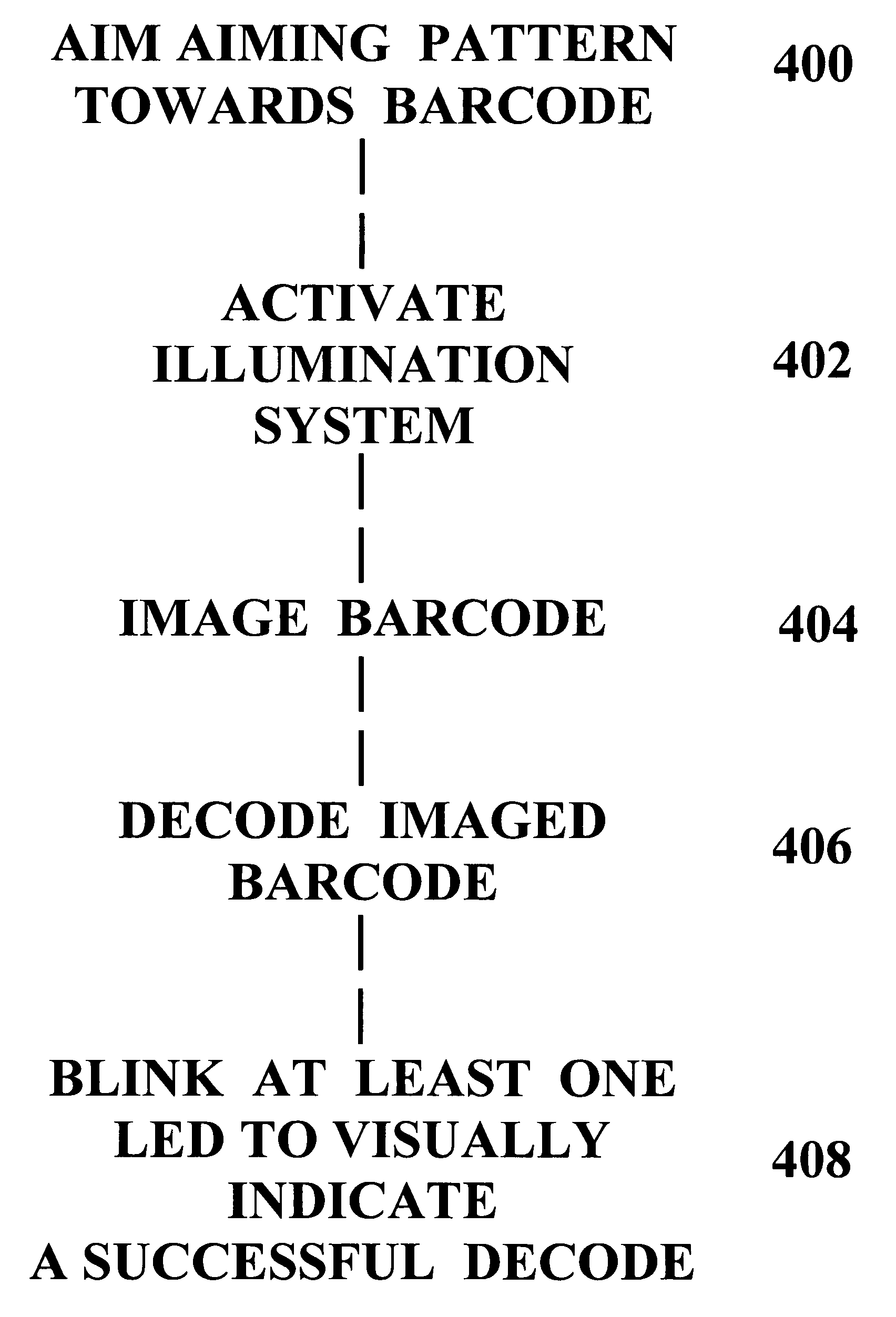
[0033] As described in detail in this section, the present disclosure provides a barcode imaging / decoding system having improved visual decoding indication that overcomes the shortcomings of prior art barcode imaging / decoding systems and as prior art laser barcode scanning / decoding systems. In both type of systems, a barcode is read (either by imaging or laser scanning) and decoded as known in the art.

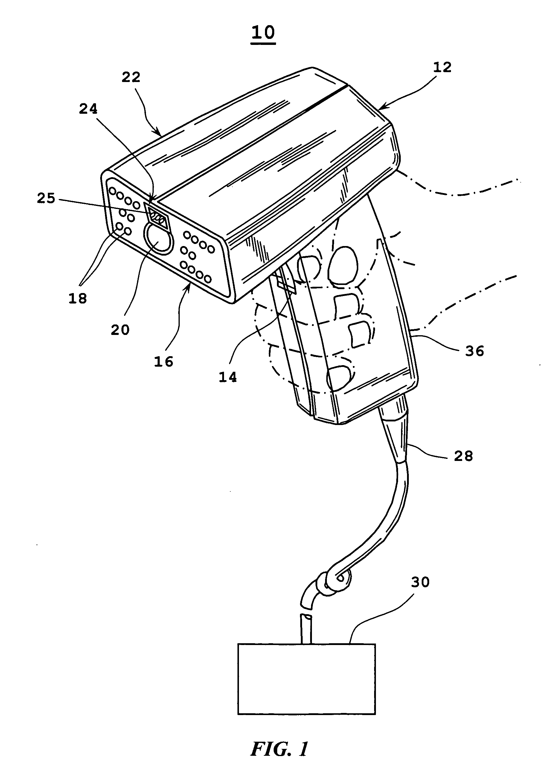
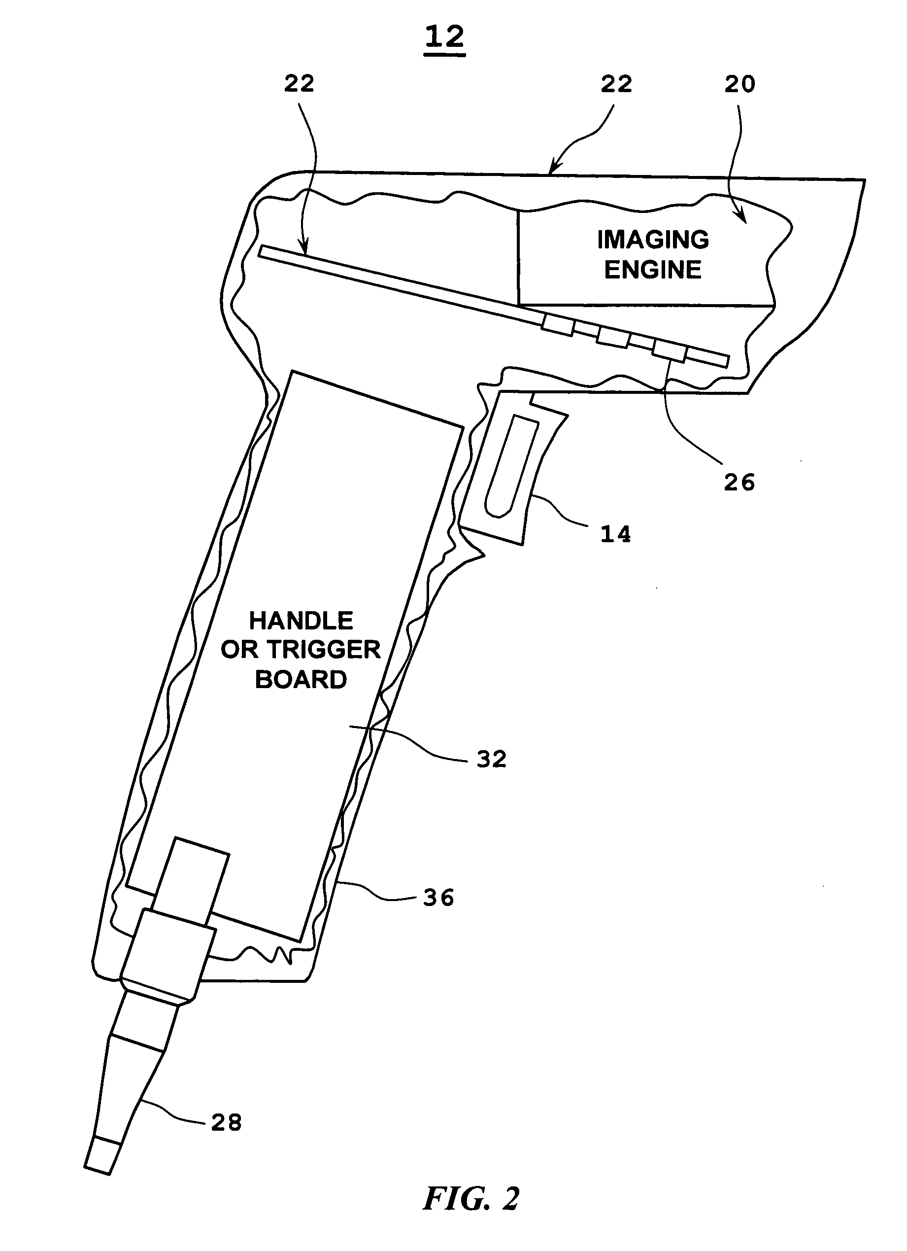
[0034] The system 10 as shown by FIG. 1 includes a barcode scanner 12 having a trigger switch 14 for being operated in a trigger-operated mode, an illumination system 16 having a plurality of LEDs 18, and an imaging engine 20 encased within a housing 22. The imaging engine as known in the art includes a lens assembly and a sensor array, such as a CCD or CMOS sensor array, for imaging a barcode located in a field of view of the imaging engine 20 upon activation of the trigger switch 14 and the illumination system 16. The sensor array can be a one-dimensional sensor array as used in lin...


PUM


Abstract

Barcode imaging and laser scanning systems are disclosed having at least one processor storing barcode decoding algorithms each corresponding to a respective symbology. The at least one processor causes at least one LED and/or a projected laser beam of the barcode imaging system to blink by rapidly turning it off and on one time or several times whenever a successful decode occurs. In the laser scanning system, the at least one processor causes a projected laser beam to be blinked by turning a laser beam system off and on one time or several times whenever a successful decode occurs. The act of blinking the at least one LED and/or the projected laser beam in the barcode imaging system or the act of blinking the projected laser beam in the laser scanning system provides a visual indication to a user of a successful decode. The act of blinking can also be used to visually indicate other information to a user. The act of blinking can be replaced by the act of changing the brightness of the at least one LED and/or projected laser beam in the barcode scanning systems.

Description

BACKGROUND OF THE INVENTION [0001] 1. Technical Field [0002] The present disclosure relates generally to barcode imaging and laser scanning systems. In particularly, the present disclosure relates to barcode imaging and laser scanning systems having improved visual decoding indication. [0003] 2. Description of the Prior Art [0004] Handheld barcode systems that use linear sensor arrays or a laser beam to capture an image of a single line across a barcode are common, such as used in point-of-sale systems. A barcode scanner of a barcode imaging system usually includes an illumination system which shines light on the barcode in the area where an image sensor is aimed, so as to improve the quality of the image that is captured by the image sensor and to eliminate total dependency on ambient light conditions. [0005] For best performance, typically in barcode imaging systems, the light projected from the illumination system is concentrated as much as possible on the line that is scanned by...

Claims


Application Information

Patent Timeline
Patent Type & Authority Applications(United States)
IPC IPC(8): G06K7/10
CPCG06K7/10732
Inventor BARKAN, EDWARD
Owner SYMBOL TECH LLC
Why Eureka
Try Eureka