Universal stand for vehicle engines and gearboxes

Inactive Publication Date: 2006-06-01
NIKOLIC LJUBOMIR
View PDF11 Cites 15 Cited by
  • Summary
  • Abstract
  • Description
  • Claims
  • Application Information

AI Technical Summary

Benefits of technology

[0013] It is the primary object of the invention to provide an improved engine and gearbox stand having a movable support assembly adjusted to move by a foot capable

Problems solved by technology

However disadvantage is that the carrying plates of these devices are so close and parallel to rear side of engine and gearbox respectively and disable or substantially hinder access to rear side thereof such that work therein cannot be done while engine and gearbox respectively is on these devices.
But, disadvantage of these devices is they disable or substantially hinder access to bolted sides of engine and the close position of pivoted carrier or swivel-rails in relation to respective frames may prevent full rotation of mounted engine if it has extended or coupled part(s) on its block(s).
Both of these kinds of devices enable clear access to every side of engine, however, their disadvantage is that they are intended on

Method used


Image

  • Universal stand for vehicle engines and gearboxes
  • Universal stand for vehicle engines and gearboxes
  • Universal stand for vehicle engines and gearboxes

Examples


Embodiment Construction

[0031] Reference will now be made in detail to the present preferred embodiment of invention, an example of which is illustrated in the accompanying drawings.

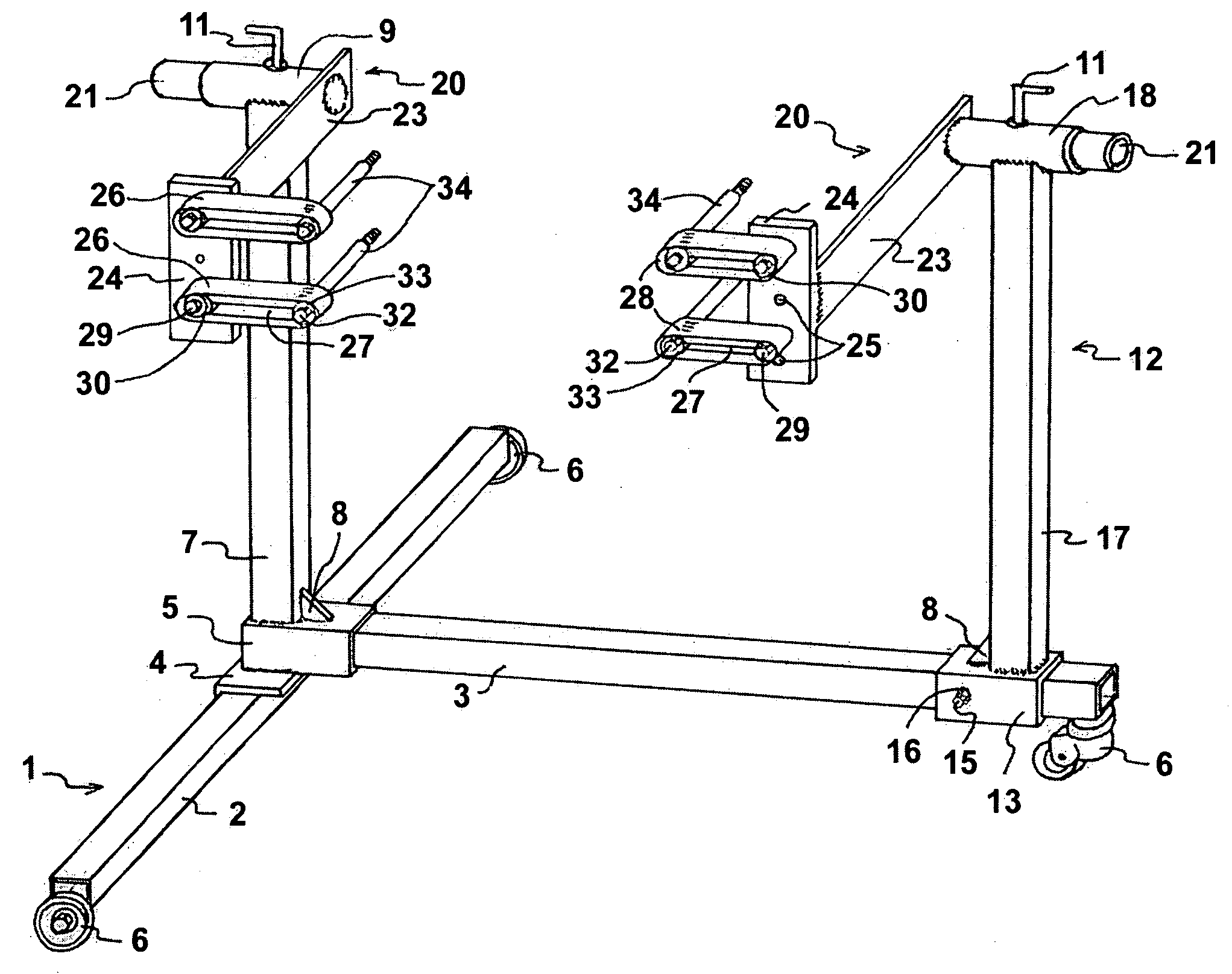
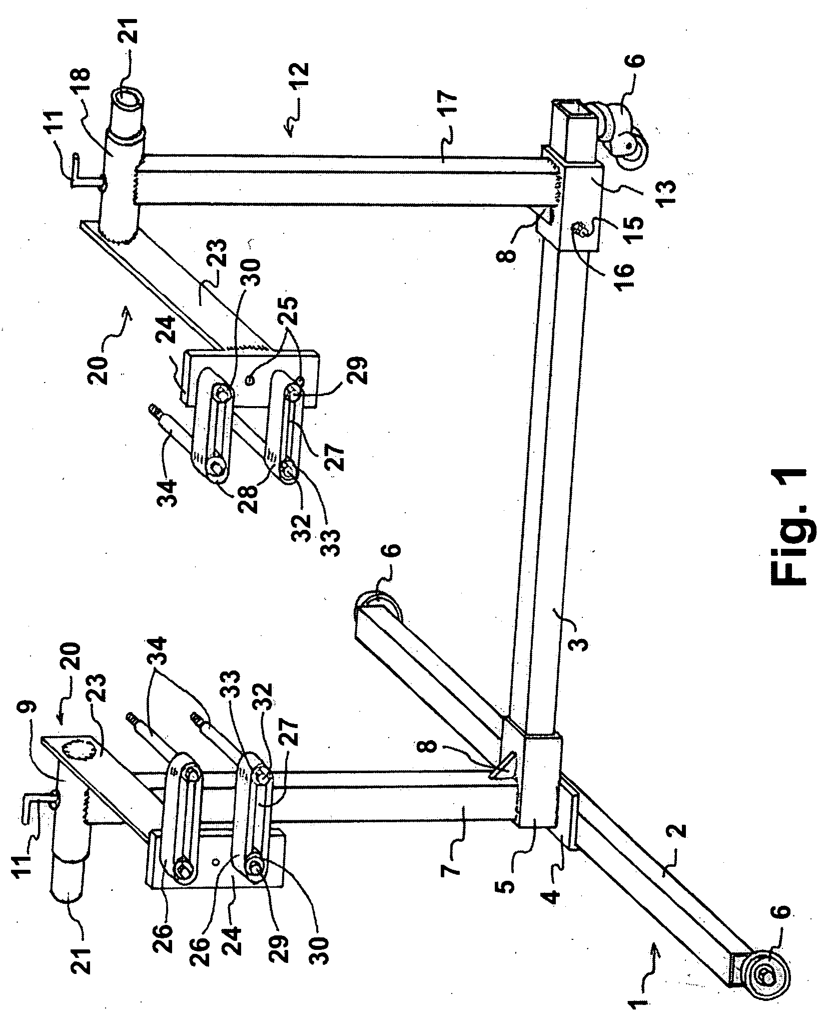
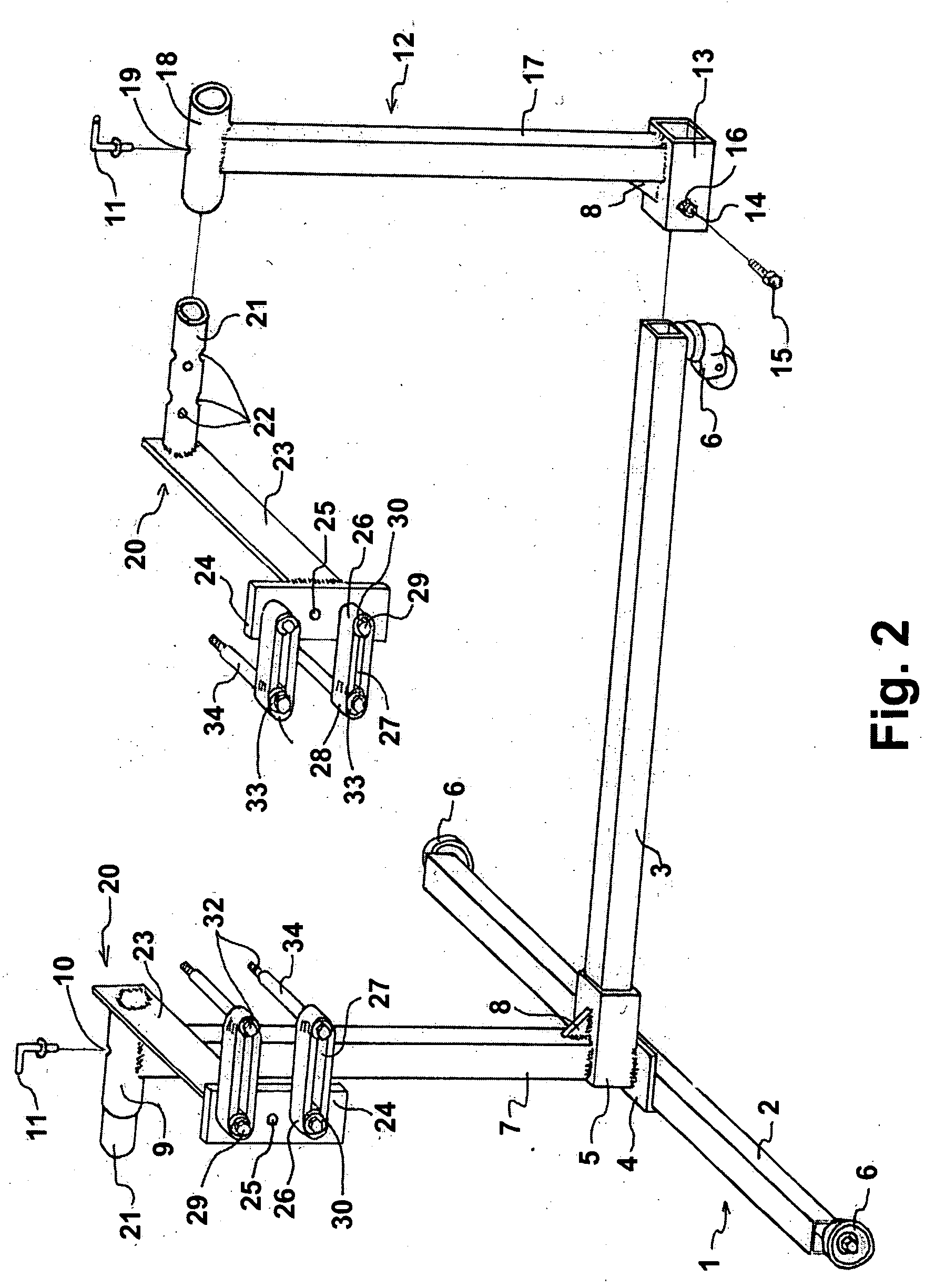
[0032] Referring to FIGS. 1 and 2, it may be seen that the stand includes a base structure (1). The base structure is of known design and it will not be described in detail. Briefly, in the illustrated embodiment two legs (2,3) forming T-shape of the base structure are assembled by way a L-shaped means (4) and a connecting means (5). The L-shaped means and the connecting means are rather welded to each another. The base structure is placed on wheels (6), rather one of which is castor to insure fully horizontal mobility of the stand around the floor. The stand further, in the illustrated embodiment, includes an existing immovable column (7) which is firmly attached by lower end to the connecting means (5) and may be strengthened in that position by strengthening means (8) which may be any suitable strengthening means. Existing ...


PUM


Abstract

A stand holding virtually any vehicle engine and gearbox respectively during repair and renovation allowing clear access to every side of thereof, carrying a base structure (1) an immovable column (7), a horizontal immovable tube (9), includes a movable support assembly (12) and a pair of rotatable adjustable carrier assemblies (20) being distanced from one another. The support assembly is capable of varying the distance between a pair of carrier assemblies to correspond with the size of engine and of gearbox respectively. Each of the pair of carrier assemblies including an arm and a carrying plate connected by way of the connecting member; rather two handles adjustably coupled to corresponding carrying plate by first ends and having bolts threaded through second ends and corresponding adapters for receipt within corresponding holes of engine and gearbox respectively. The arms rotatably and adjustably threaded through horizontal tube (9) and horizontal support member (18) respectively such that carrier assemblies being positioned inside of the device between column (7) and vertical support member (17) to hold engine and gearbox respectively to allow clear access to every side of engine and gearbox, respectively. The arms have a plurality of holes to adjust the distance between column (7) and vertical support member (17) respectively and engine and gearbox respectively.

Description

TECHNICAL FIELD [0001] This invention relates to an improved stand which provides secure holding virtually any vehicle engine and gearbox respectively during repair and renovation. BACKGROND ART [0002] Devices are known which can hold various vehicle engines and gearboxes respectively. These devices hold engine and gearbox respectively to their rear sides (engine and gearbox sides coupled to each other and enclosing clutch). However disadvantage is that the carrying plates of these devices are so close and parallel to rear side of engine and gearbox respectively and disable or substantially hinder access to rear side thereof such that work therein cannot be done while engine and gearbox respectively is on these devices. Moreover, for the same reason certain parts must first be removed from the engine (e.g. clutch, flywheel, oil seal) and gearbox (e.g. oil seal, clutch release spring, release arm, bearing guide sleeve) before being attached. Also, removed or new parts can be returned...

Claims


Application Information

Patent Timeline
IPC IPC(8): F16M11/00A47F5/00B25H1/00
CPCB25H1/0007
Inventor NIKOLIC, LJUBOMIR
Owner NIKOLIC LJUBOMIR
Why Eureka
Try Eureka