[0027] The back-projection screens used may be of any desired type and quality. However, it is an
advantage of the present invention that the screens can be of lower quality and cost while still providing a high degree of visual fidelity and realistic depth of vision at appropriate distances. Screens may be flexible or rigid, may have any desired
viewing cone (e.g. 70° to 180°), may be of any desired screen ratio, and may have any desired light
gain (e.g. 0.5 to 2.5). Some examples of screens include Da-Tex™, Dual Vision™, Da-Plex™ and Dai-Nippon™ (products from Da-Lite Screen Company Inc. of Indiana), and Cineflex™, Cinefold™, Cineperm™, DiamondScreen™ and IRUS (products from Draper company).
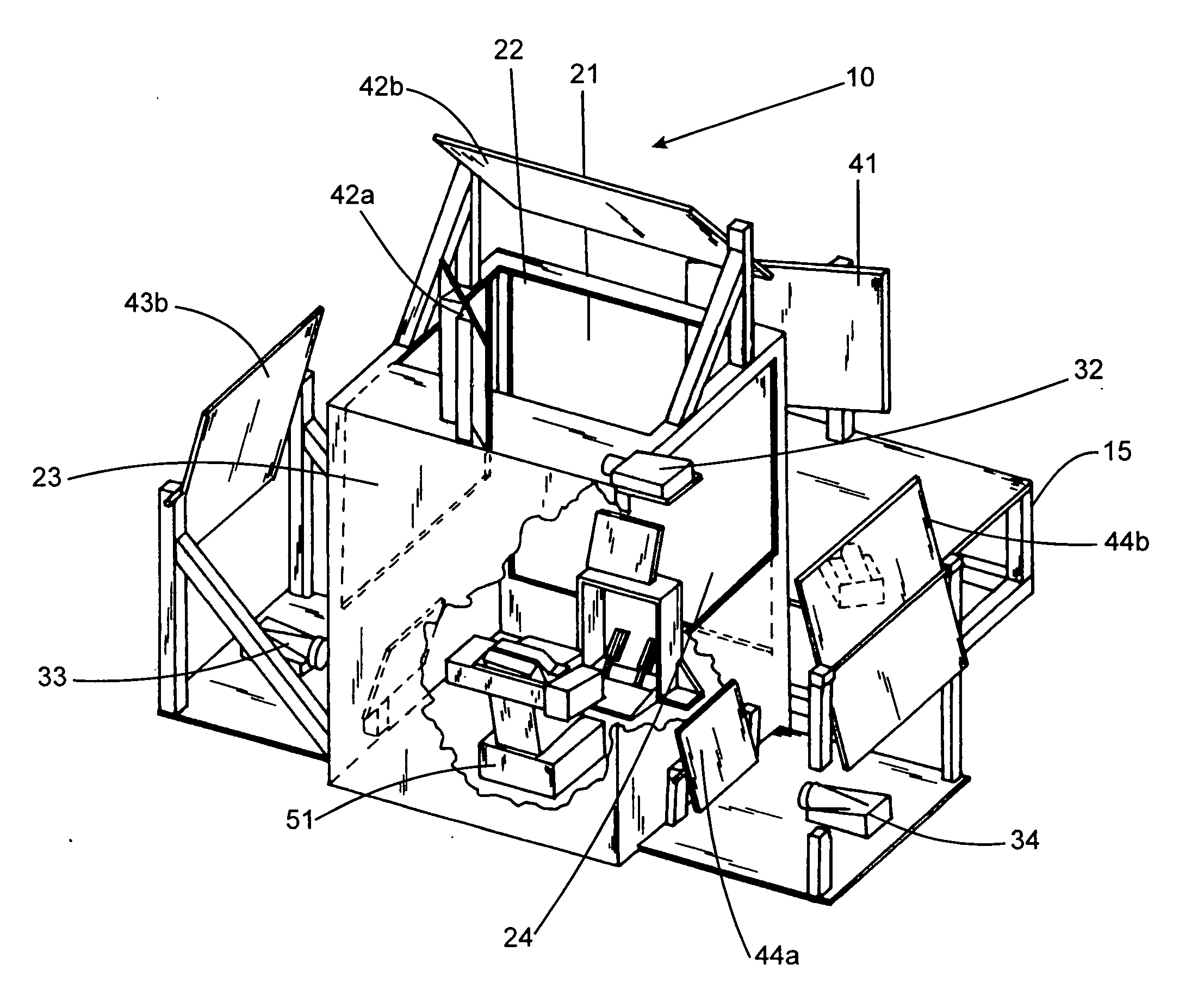
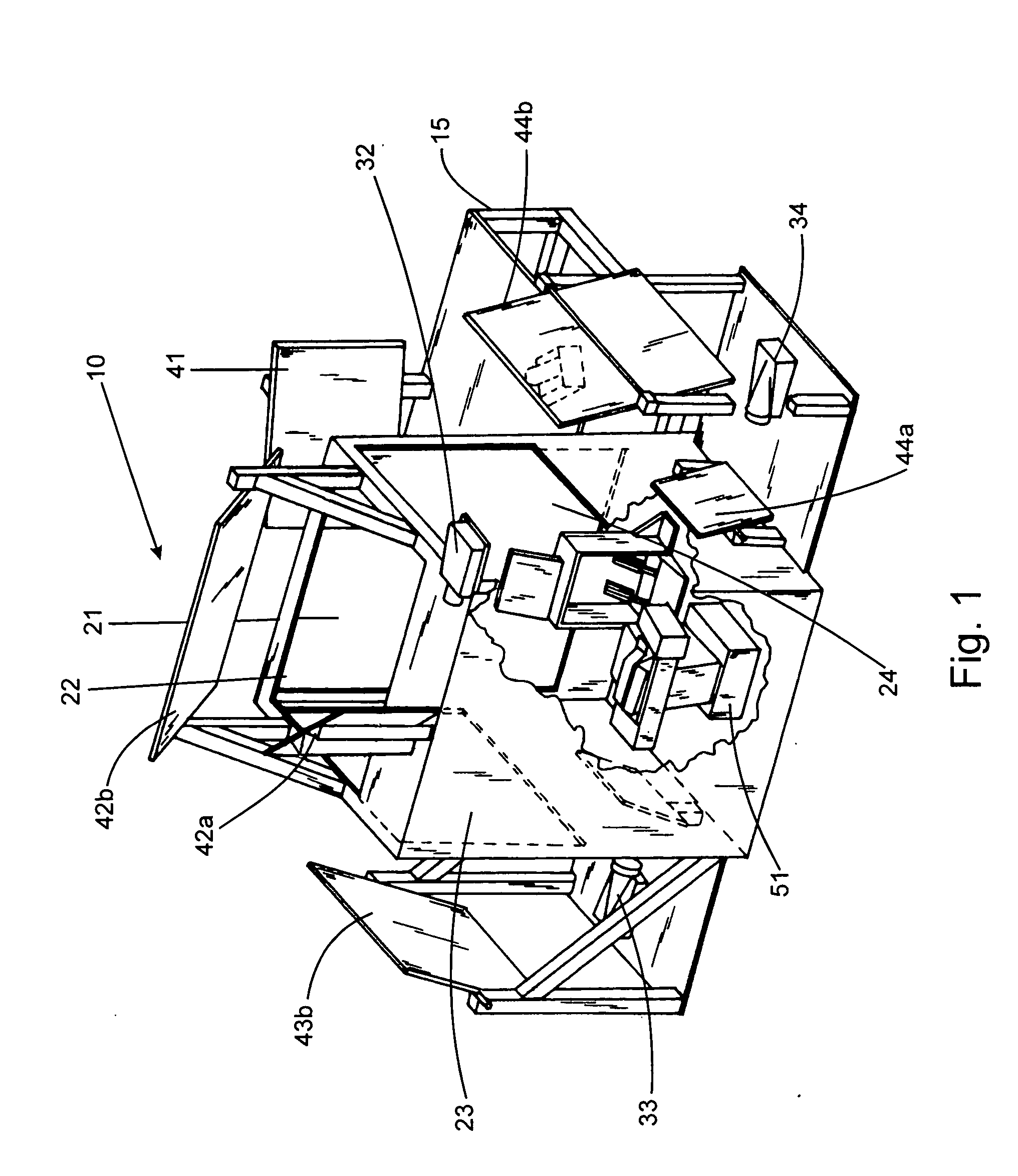
[0028] Projectors are used to project pairs of offset images on to the back of the screens so that each pair of offset images depicts a view out of one of the windows. Consequently, projectors must be placed so that they can project images on to the back of the screens. Projectors may be placed directly behind the screens, or, through the use of mirrors (as further described below) projectors may be placed almost anywhere in the simulation space. Any suitable
projector may be used. However, it is an
advantage of the present invention that the projectors can be of lower resolution and cost while still providing a high degree of visual fidelity and realistic depth of vision at appropriate distances. For example, the present invention may employ 84 Hz and up projectors at a resolution as low as 640×480 while projectors for
CAVE™ systems are typically 96-120 Hz with a resolution of 2000×1024. In addition, the projectors used in the present invention need only project part of a
virtual world, whereas projectors used in a
CAVE™
system need to project a whole
virtual world. Therefore, less expensive projectors may be used in the present invention. Examples of projectors useful in the present invention include, for example, a Seleco™ SDV100 or a Seleco™ SDV250
projector.
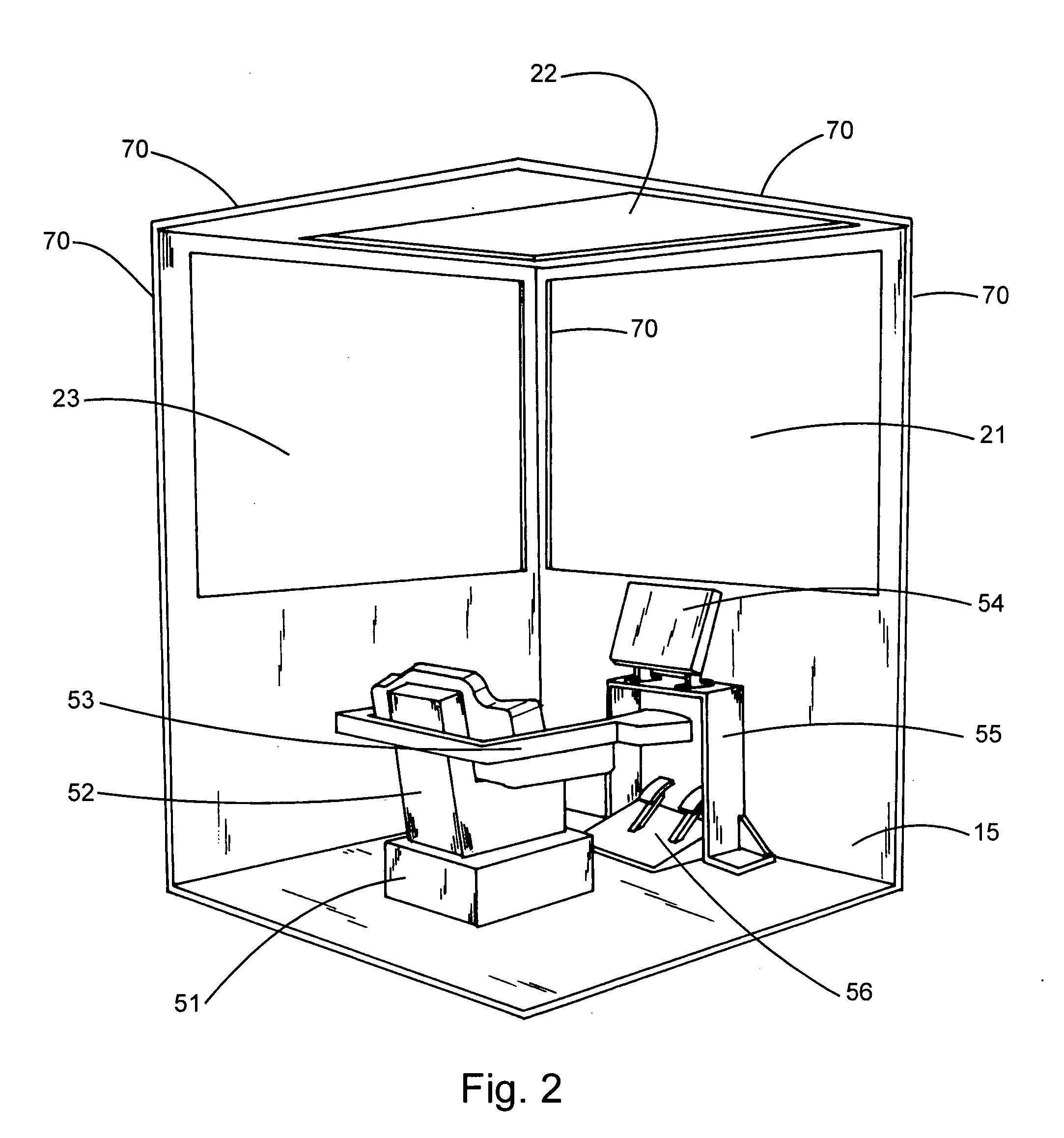
[0029] The pairs of offset images may be resolved into 3D stereo images by any suitable means. In this embodiment, an operator may wear a pair of stereo
shutter glasses. The 3D stereo images seen on the screens by the operator represent 3D virtual views out of the windows of the realistic visual environment. One or more of the frame elements, or other physical components, defining one or more non-windowed parts of the visual environment are perceptually integrated with one or more of the 3D virtual views to provide the realistic visual environment. For example, the frame elements between two adjacent screens may be visually perceived as the window frame between two adjacent windows of the realistic visual environment. Therefore, it is unnecessary to virtually stitch together the two separate 3D virtual views out of adjacent windows since a physical component is acting as a perceptually integrated element of the visual environment to provide an illusion of continuity. The environment may be designed so that many or all of the physical components represent something in the realistic visual environment which are perceptually integrated with the 3D virtual views, thereby providing an exceedingly realistic simulation.
[0030] As indicated above, mirrors may be used in conjunction with projectors to project images on to the back of the screens. Mirrors permit versatility in the placement of the projectors permitting a reduction in the size of the simulation space and more efficient utilization of space. Mirrors may be mounted on the frame or within their own mounting units and may be pivotable or otherwise movable to assist with proper alignment. Single bounce or multiple bounce (e.g. double bounce) mirroring systems may be used. Single bounce systems result in less dimming while multiple bounce systems offer more versatility.
[0031] Regular or first surface mirrors may be used. Regular mirrors are cheaper, however, reflected light is dimmed by regular mirrors as well as associated light
refraction issues. First surface mirrors, for example Mirrorlite™ from Hudson Photographic Industries, Inc., New York provide better
light reflection but are more expensive. The size of the mirrors depends on the relationship between the width of the
light cone produced by the
projector, the distance from the projector to the screen, the angles and locations in which the mirrors have to be placed. One skilled in the art can readily determine the number of mirrors required and their sizes based on the projected light path within a particular simulation space. Flat mirrors are desirable where dimensional accuracy is required. Alignment of the mirrors is important and once alignment is achieved the mirrors should be fixed rigidly in place to avoid
distortion or misalignment of the image on screen.
[0032] The simulation space may comprise other physical components to enhance realism of the simulation or to provide
structural integrity or aesthetic effect to the simulation space. Some examples include light shielding, operator displays, operator controls, seats,
doors,
stairs, handrails, etc. In order to shield the visual environment against unwanted light, curtains, panels or other shrouding elements may be employed and / or physical components may be painted an unreflective color, e.g. black. Operator displays may take any suitable form, for example, consoles or dashboards with video displays, gauges, LED read-outs, etc. Operator controls may take any suitable form, for example, joysticks, buttons, levers, wheels, foot pedals, dials, etc. Seats,
doors,
stairs and handrails may be used when the real
operating environment uses them or when necessary to provide comfort or safety to the operator.

